Build Day 22: Engine Start

The build is practically over now and it time for the moment of truth !

Bleeding the clutch and brakes: The clutch release bearing is hydraulically operated so we filled the clutch cylinder and attached a bleed bottle to the extended bleed valve that protrudes from the slot in the bellhousing. An 8mm spanner is needed to to loosen the bleed valves and after a few pumps of the clutch pedal to fill the system the clutch was working properly.

The brakes required more effort because of the longer hose / pipe runs, split circuit and 4-pot front calipers. We used a pneumatic brake bleeding system that slightly pressurised the system via the brake fluid reservoir to force fluid through the system. We started with the left rear caliper as this is the furthest away from the reservoir and then worked our way round; right rear, left front outer, left front inner, right front outer, right front inner. The initial results were better than I expected but it took another 4 complete rounds of bleeding and tightening connections to get all air out of the system.

Oil: The 420R has a dry sump which requires 4 litres in the tank and 3litres fill via the engine. I used the synthetic oil supplied by Caterham for the initial start but this will be drained out and replaced with Millers Running In oil when the car goes for a professional run-in and tune up by Stuart at Premier Power. To test for fuel pressure I disconnected the fuel cutoff inertia switch (although not really necessary as there was no fuel in the tank at all) and then turned the engine over with the iginition on. After about 20 seconds of cranking we began to see oil pressure which was a big relief.

Coolant: Caterham supply 5L of pre-mixed coolant which is barely enough in my opinion so I bought some more and ended up adding another 1L to the system

Fuel and Engine Start: I filled the tank with about 25L of standard unleaded petrol and we were now ready for the engine start. We pushed the car outside, turned on the ignition and tried the starter. The engine turned over nicely and we saw good oil pressure but the engine refused to start. We stopped after a few attempts and pushed the car back into the garage to figure out what was wrong. I also put the battery back on charge whilst we thought about the problem.

I could not smell any fuel on the initial attempt and all the dash electrics seemed to work so I thought i would top up the tank with another 10L of petrol as I had heard that the fuel pump can have difficulties self-priming. I also checked the fuel cutoff switch was connected and properly reset.

Sitting in the car I flicked the starter and was somewhat surprised (and pleased) when the engine burst into life. The initial idle was a little uncertain but it settled down as the engine warmed up indicating that the lambda sensor was working.

With everything running I depressed the clutch, put it into first gear and rolled out of the garage under power. A few very short runs up and down the drive (with each family member taking turns as passenger) proved the clutch, brakes and reverse gear all worked. The radiator fan came on at about 100 C so with everything checking out I backed into the garage and shut the engine down.

Leaks: There were a couple of leaks, one at the submarine and the other at the radiator top hose. I went round and tightened all the clamps and seemed to fixed the issues.
Build Day 21: Lights and Electrics

I left the lights and electrics to the last part of the build as I was waiting for some carbon fibre parts to arrive. In the end due to shipping delays I ended up installing the the parts that came with the kit and then swapped them out when the carbon items I ordered a long time ago eventually turned up.

The headlights sit on stalks that are fixed to the forward upper wishbone mount. There is a hollow bolt that passes through the indicator pods and then through a bush on the end of the stalk. All the wires have to be passed through the bolt and then fed through the stalk itself. They then come out of the end of the stalk and pass through the wishbone mount. Once through the wishbone mount the wires are gathered together and terminated in an Econoseal connector.

The wire from the indicator repeater passed through the cycle wing stay and then along the upper wishbone into the body where it is joined with the other wires in the Econoseal connector. The connector then plugs into its counterpart on the main wiring loom.

This whole process is repeated on the other side.

Care has to be taken to protect the wires with heat shrink tubing or silicone hose. Rubber grommets have to be fitted wherever a wire or bundle of wires enters or exits the cycle wing stay / headlight mount. A grommet is also required on the upper wishbone mounts (fitted earlier in the build).

There is not a lot of room to work with and patience is needed when feeding the wires through the various tubes. Fitting grommets can be frustrating as you never believe it is going to fit but patience, silicone lube and plastic trim levers helped to manipulate them into place…eventually.

I connected the battery after all this work and proceeded to test the electrics. Success with the headlights but the indicators failed to work and kept blowing a fuse. After disconnecting and then selectively reconnecting the lights I traced the problem to a short in the left hand indicator pod. Pulling it apart revealed that the spring loaded central connector had come loose and was causing the short, a quick fix with the needle nose pliers and I now had functioning electrics.

With the electrics all working the last stage is to bleed the brakes and clutch and fill up coolant and engine oil before starting the engine.

Build Day 20: Boot carpet, Washer Bottle and Differential Oil fill

We are nearing the end of the build now and one of the last jobs is to fill the differential with oil. The oil is supplied with the kit and no additive is required either. The differential fill plug is not easy to get at so I lifted the aluminium honeycomb panel to get access.

I made up a filling tube and funnel which I attached to the rollbar with masking tape. The differential requires 0.8L and so I gradually filled it up letting gravity do the work. The oil stinks of sulphur so I was very careful not to spill any and left the tube in place for 30mins to ensure it all drained through before refitting the drain plug and closing up the boot.

Washer Bottle: The washer bottle can either be fixed to the side panel or the petrol filler tube cover – I chose the latter as this is how Caterham do it on their factory productions cars. After carefully measuring the height of the bracket we drilled holes for the bracket, washer pipe and electrical connections. Most of the wiring and tubing is tucked behind the filler cover and I used a couple of rubber grommets to prevent chaffing of the electrical and washer pipe. The cover is simple screwed into the honeycomb floor (unfortunately I had no option but to use a couple of self-tapping screws)

Boot Carpet: The carpet is pre-cut in several sections including a set of triangular pieces for the rear bulkhead which I chose not to fit. I used the same contact adhesive as for the tunnel carpet and after some trimming with a Stanley knife I got the panels to fit to my satisfaction. I left the boot floor carpet loose as I may need access to the handbrake adjuster under the wooden part of the boot floor later.

Build Day 19: Front and Rear Wheel Arches

Rear Wheel Arches: Before fitting the GRP rear wheel arches I sprayed the undersides with Hammerite Underbody Seal to reduce the chance of star cracks in the gelcoat caused by stones flying up from the wheels.

Installation is simple – a length of rubber seal with a piped edge goes between the chassis and the wheel arch and the wheel arches are bolted to the chassis. A small section of the inner rim needs to be opened up with a Dremel to allow the radius arm to swing freely.

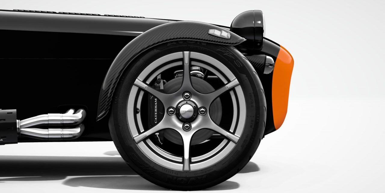
The carbon stone guards are usually fitted with rivets but I preferred to use 4mm bolts to give a neater finish and allow easy removal of the panel when they need replacing.

Front Cycle Wings: The front cycle wings are bonded to the wing stays using the Teroson adhesive supplied with the kit. There are stories of wings flying off with air pressure pulling the powder coat off the metal of the wing stay. To avoid this we removed all the powder coat and roughed up the area to be bonded with a file. The wings are installed in two stages:

  1. A ‘sausage’ of adhesive is applied to the top of the wing stay and the cycle wing carefully positioned and held in place overnight with masking tape to allow the adhesive to cure. Care needs to be taken to ensure the cycle wings are level and the leading edge is in front of the wheel rim (we used a plumb bob to check this).
  2. More adhesive is applied around the original bond and smoothed over. I made sure the adhesive wrapped around the whole wing stay tube.

Build Day 18: Seats and Harnesses

Harnesses: The harnesses have to be fitted before the seats as there is simply no access to the fittings once the seats are in place.

The harnesses are handed and should be installed so that the end with the red buckle is inboard (ie bolted to the transmission tunnel. There are two fixing points and the forward most position must be used if you have the Tillet bucket seats.

Caterham supply a 4-point racing harness as standard on the ‘R’ specification (made by Luke). The buckle also has provision for a crutch strap to create a 6-point harness. I think these are worthwhile as tightening the shoulder straps pulls the lap belts up toward your diaphram which is not good and overtightening the lap belts to compensate is uncomfortable.

The harnesses come supplied with the correct specification of bolts, washers and spacers to allow the belts to swivel once the bolts are tightened up. Instructions are provided with the harnesses and installation is fairly easy. Once the bolts were torqued to specification and paint marked it was time to move onto the seats.

Seats: I have the Tillet padded race seats which are basically a carbon fibre bucket seat with two sections of thin padding. I find them really comfortable.

The seats are a very tight fit in the chassis and whilst there is nothing complicated about their installation it is an awkward job where two pairs of hands really help, particularly in the final stages.

The first step is to fit the runners:

  • The drivers side runners are adjustable in terms of fore/aft movement but the release lever fouls the lowered floor bracket. After trying to bend it in order to get the necessary clearance I gave up and simply cut it short and put one of the rubber bungs that came wiht the heater over the cut end. I can reach under the seat with my fingers to lift the lever and release the mechanism but the movement is so small (8-10cm) and I will be the only driver so I think I will leave the seat in the rear most position and forget about it.
  • The passenger seat is mounted on two fixed aluminium runners that bolt to the seat.
  • Both passenger and drivers seats require thick nylon spacers between the seat and the runner.

Caterham have recently changed the fixing pack for these seats which initially caused some confusion. The new illustrated manual shows the runners are bolted through the floor pan using cap head bolts and nyloc nuts. However, I was supplied with two fixing packs (one for each seat ?) that contained a range of fittings including 8 black countersunk bolts and 8 large countersunk washers. It was not obvious how to fit the seats wiht the 16 countersunk bolts and washers and other fittings but a quick consultation on the Caterham Tech Talk Facebook page demystified everything.

  • Caterham had sent me two fixing packs – but I only needed one pack for both seats.
  • The new method of fitting the seats does away with the cap-head bolts and nylocs and uses the countersunk bolts the pass up from the ground into captive nuts in the seat runners.

Once the mystery was solved it was a relatively straightforward to fix the seats with the only difficulty being locating the captive bolts in the seats. This is where a second pair of hands is really helpful to manouvre the seat around from the top whilst I tried to line up the bolts from underneath. Once one bolt is loosely fitted the others tend to go in fairly easily.

I think this new arrangement is easier, neater and reduces the chances of the protruding seat bolts grounding out on speed bumps.

Build Day 17: Steering Wheel and Shift Lights

Sequential Shift Lights: Although the 420R is fitted with a shift light (the single LED you can see between the dials) it only illuminates at maximum revs so is of limited use.

I ordered the sequential shift lights from Caterham, these are made by ACES but with Caterham branding and consist of a dash mounted display unit and a control unit. The light on the left is a green ‘low rev’ light and the five to the right are 3 amber and 2 red that light up in sequence and indicate when to change up without having to look at the rev counter. I’ll programme this correctly once the engine is run in and tuned up.

Fitting the unit was quite difficult mostly due to limited access behind the dash which is stuffed full of wiring. I knew that the wiring loom was pre-wired for the shift lights so it was just a matter of finding the right connectors. This is where the iPhone camera comes in handy by sticking it up behind the dash and taking random pictures to see what is there.

After rummaging around and unclipping a few cable ties I found three connectors tied together, these are the live, earth and tacho feed I needed for the control unit.

The control unit wiring needed shortening and new connectors soldered into place but once this was done it was a relatively easy job to fit the control unit under the dash.

To fit the display unit I had to drill a 25mm hole in the dash to allowed the shielded terminal to pass through. This was a little nerve-wracking knowing the mass of wiring underneath and also required removal of the windscreen! The hole is sealed with the grommet that was pre-fitted to the cable. I used a couple of strips of dual-lock tape to fix the unit to the dash.

More dual-lock tape was used to fix the control unit which is tucked up out of the way by the steering column.

Steering Wheel: I have the quick release steering column that allows for easy removal of the steering wheel (I’ll have to take it with me if I park up in a public place). The column is in two parts that slide over each other to allow it to collapse in the unfortunate event of a collision. The lower part runs from the universal joint on the steering rack through the tunnel firewall to thread into the steering column tube that runs from the dash to the scuttle. The upper part threads down through the steering column tube to fit over the lower part. Both parts are held together with a clamp. A bush at the top and bottom of the steering column tube keep everything nice and tight.

Build Day 16: Carbon Panel Fit

Fitting the carbon interior panels was an extra job I could have avoided if I had specified them at the outset. By the time I decided I wanted to go down this route it was too late to amend the order but Caterham were happy to supply a set as aftersales parts.

Removing the original aluminium panels was covered in an earlier post and the time had come to fit the nice new carbon ones. I had obtained black aluminium rivets for the sides and black stainless ones for the floor seam (this is a structural consideration and Caterham use heavy duty bright stainless rivets in this area).

I was also going to fit the interior knee panels and fuse box cover at this stage. Caterham use self tapping screws for the knee panels as the panels have to be removed in order to access the windcreen stanchion bolts (e.g. to fit an aeroscreen or replace a windscreen). I hate self-tappers and prefer to use machine screws which require drilling and tapping but are easier to install and remove.

The rear panel went in first using a fair amount of RTV sealant between the panel and the chassis members. I dry-fit the panels a couple of times before applying the sealant to work out how to manouvre the panel in place. The tabs on the main tunnel had to be folded flat against the tunnel wall in order to provide enough clearance.

I also made sure I sealed the corners of the lowered floor panels. Although the silicone made the process somewhat messy the panel went in without any real trouble and all the rivet holes lined up. This was where the air rivet gun came into its own – much less effort and greatly reduced chance of slipping and marring the surface.

The side panels went in without any trouble, in fact it was much easier installing the new panels than it was pulling the old ones out. Again the air rivet gun was invaluable, particularly with the stainless rivets which require about 3 times the effort to install compared to the alumnium ones.

I drilled and tapped the holes along the upper edge of the side panels where the knee panels go. The holes in the panels lined up perfectly so the drill was just to clean out the hole and it was an easy job with a 4mm hand tap the prepare for the machine screws.

The final interior panels to fit are the ‘keystone’ panels that cover the bow tubes. I had to mark and drill the holes in the back panel but everything went well. At the time of installation I was waiting for the carbon fibre bow tube protectors so I left this area un riveted but the rear panel and interior footwell panels were securely riveted in place.

UPDATE: The bow tube protectors arrived from Classic Carbon and finish this area off nicely which is vulnerable to scratches and chipping from the harnesses as you get in and out.

Knee Panels and Fuse Box Cover: The knee panels can be quite a problem to fit as it is very difficult to get the holes to line up. The bottom edge of the knee panel is slotted in between the chassis and the interior panel. It then has to be pulled toward the dashboard so that the edge fits above the rolled bottom edge of the dash. Lining the holes up is very difficult and other builders have just drilled new holes into the knee panels. I found a tip from Chris Collins very helpful here. Simply using a piece of masking tape on the knee panel and marking the position of the holes makes lining everything up a lot easier as the fore/aft alignment is taken care of. Once I’d got one screw loosely in place though the others went in quite easily.

The fuse box like the knee panels requires a bit of preparation involving gluing more rubber edge trim along the non-radiused edges. The fuse box cover also houses the 12V socket outlet (useful as a charger port) and is fixed in place with 3M ‘Dual lock’ tape (a stronger version of ‘velcro’).

The final job in this area was to fit the rubber floor mats. These are handed and require press-stud bases to be riveted to the floor and the press-stud fasteners to be riveted to the mats themselves – all fairly straightforward.

Build Day 15: Plenum Refit and Throttle Cable

We removed the plenum chamber and throttle body to help with the engine installation and plumbing (in fact I think it is impossible to route all the coolant pipes with it in place).

Refitting is very simple, just a matter of bolting it back on. A couple of the bolts are difficult to access but a combination of socket extensions and wobble bars did the job.

We also installed the airbox and air filter which simply mounts on three rubber bobbins just in front of the scuttle on the passenger side. A piece of rubber edge seal needs to be fitted to the airbox intake, the rubber flange will form a seal against the bonnet intake.

The throttle cable ‘plugs’ into the pedal box and arcs around the front of the engine to loop back and terminate in the throttle body. The nipple on the pedal box end slots into the throttle pedal. The throttle pedal slot required a little adjustment and deburring with a Dremel until I was happy that the cable was secure but would not chafe during use (it may be worth purchasing a spare throttle cable and keeping it in the boot as a precaution).

The throttle pedal and throttle stop need adjusting to ensure a full range of movement on the throttle body. This involved bending the upper part of the throttle pedal backwards and lowering the pedal stop (apparently this is entirely normal). I managed to get a full range of movement and the final act was to put a blob of silicone sealant in the top of the pedal to stop the cable from jumping out before refitting the pedal box cover. I had also read that some IVA inspectors like to see the ‘plug’ secured where it attaches to the pedal box – I drilled and tapped a small hole to accept a 4mm cap-head screw as a retainer.

UPDATE: Caterham supply a Banner lead-acid starting battery as standard. Nothing wrong with this except there are lighter options out there these days.

Once all the electrics are sorted I will swap the Banner unit out with a Lithium Ion Phosphate battery from Jack Webber Motorsport. The cost of these batteries has fallen dramatically in the last couple of years and they bring several advantages, the most obvious is the weight saving. The new JWM battery is about a quarter of the weight of the lead acid battery.

I had to fabricate a simple mount using two pieces of aluminium bar and nylon spacers. The test fit worked fine, I’ll rearrange the wiring later.

Build Day 14: Rear Suspension

There are a lot of parts to assemble in order to complete the rear suspension:

DeDion tube: The ‘Ears’, Rear Hubs, Discs, Drop-link brackets Speed Sensor and Rear Brake calipers all mount to the DeDion Tube. Before installing I gave the inside of the tube a liberal coating of ‘waxoyl’ anti-corrosion spray.

The rigid copper brake lines have to be attached to the DeDion tube using P-clips riveted to the tube itself.

Radius Arms: The radius arms control the rotational movement of DeDion tube and affect the ride and handling. One end of the radius arm mounts on the chassis and the other directly to the DeDion tube. There are two mounting points on chassis, we used the lower one as this is an ‘R’ spec car (the upper mount is used in ‘S’ spec cars and give a slightly softer ride).

A-frame: The A-frame controls the lateral movement of the rear suspension. The apex of the A-frame mounts onto the centre point of the DeDion tube and must be carefully spaced so that the distance between the face of the DeDion Tube and the chassis rail is equal on both sides. This required a lot of careful measuring and the use of spacer washers between the A-frame and chassis mounts. Whilst the spacing has to be equal there must also be no play between the A-frame bushing and the chassis rail.

By this time in the build Michael & I were getting used to using pin-punches and the nylon dead blow hammer to install tight fitting washer / spacer packs.

DeDion Ears: These are nicely machined aluminium mounting brackets that attach to each end of the DeDion tube. The hubs and one half of the brake caliper assembly mount onto the DeDion Ears. The only way to adjust rear toe in / out on a Caterham with rear DeDion suspension is to fit shims between the main tube and the ‘ears’.

After about 500miles all the suspension parts should have settled in and I will get the suspension professionally setup (toe-in, bump-steer, ride height). Chances are that rear-shims will not be needed but in case they are I chose not use silicone sealant between the Ears and the DeDion tube as illustrated in the manual as this would need to be scraped off and could interfere with the shim spacing.

In the main picture above the two DeDion Ears are on the bench by Michael’s left hand with one of the hubs just above them, a rear brake caliper and rear disk are further to the left.

Rear Dampers: The bottom damper bolts to the DeDion tube and the top is bolted to the chassis directly underneath the track-day rollbar fixing bolt (the track-day rollbar has to be fitted before the rear dampers)

Rear anti-rollbar: The rear anti-rollbar is a torsion bar that is connected to the DeDion tube via drop-links. Installation is a little tricky as the orange flexible bushing needs to be threaded onto the tube which involves passing it over a rectangular flat bar section and a 90 degree bend. Silicone lubricant and a flat bladed screw driver helped to persuade it into place. The two part aluminium chassis mounts have a nice ‘7’ machined into them.

Drive shafts: One end simply pushes into the differential and the other goes into the hub bearing. The drive shafts are handed so it is important to get them the right way round.

Assembly: There are a lot of bolts and washers involved in this part of the build so it is really worth laying them all out on the bench before starting to make sure the right length bolt is used in the right place.

Flexible Brake Hose: A braided flexible brake hose runs from the chassis to the T-piece on the DeDion tube. IVA regulations stipulate that this hose must have additional protection and so a piece of rubber fuel hose is split longitudinally, passed over the hose and cable tied in place.

Rear Brake Calipers: These come in two parts as it is a floating caliper design. The floating part of the caliper goes over the brake disk and is located with two dowel pins on the fixed part of the brake assembly which control the movement. Interestingly the rigid copper brake pipe connects to the floating part so there will always be a little movement in the brake pipe.

Speed sensor: The speed sensor is a tiny threaded rod with a cable attached to it. The speed sensors goes inside a nylon ‘top-hat’ spacer that mounts onto the right hand side drop-link bracket. The right hand drive shaft has a toothed ring mounted on it and the sensor ‘senses’ each tooth as it spins past. The gap between the speed sensor and the high points must be between 0.8mm and 0.9mm.

This was quite fiddly to setup but I was able to check it later in build when I connected up the electrical system. There is a tiny LED in the base of the sensor that lights up as a tooth passes underneath, it worked as I rotated the wheel by hand, let’s hope it works on the road.

Hand-brake cable: The hand-brake cable is one of the most awkward parts to fit. Each end hooks over a claw on the caliper body and the only way I could do this was to slacken the adjuster off as much as I could and use a pair of locking jaw pliers to wrestle the terminal eye over the claw.

The second difficulty is in finding a secure route for the cable that avoids fouling the driveshafts, brake and fuel lines and any moving parts of the suspension. I eventually used a P-clip on the boot floor rail as a guide and then had the cable loop underneath the drive-shaft and round to the caliper. I secured the handbrake cable to the chassis rail with cable ties and hope that this arrangement passes the IVA inspection.

Build Day 13: Trackday Rollbar

Not much to say about the rollbar other than the track-day roll bar uses 2 cap head bolts that come up from the top of the damper mount into the bottom of the rollbar and 2 hex head bolts that go through a plate on the top of rollbar down into the rear bulkhead. The last two bolts fasten the backstays to the chassis mounts in the boot.

The rollbar needs to be fitted before the rear dampers (otherwise you would need to remove the dampers to gain access to the mounting bolt).

I’d heard stories of builders struggling to align the rollbar with the mounting holes but ours went in really smoothly.