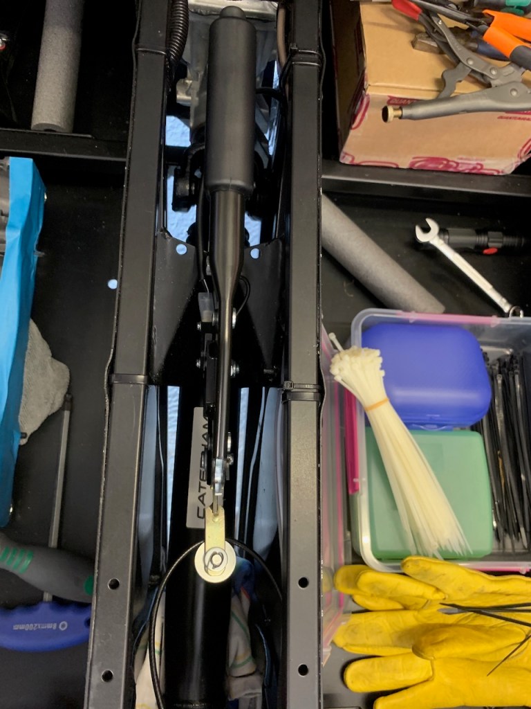
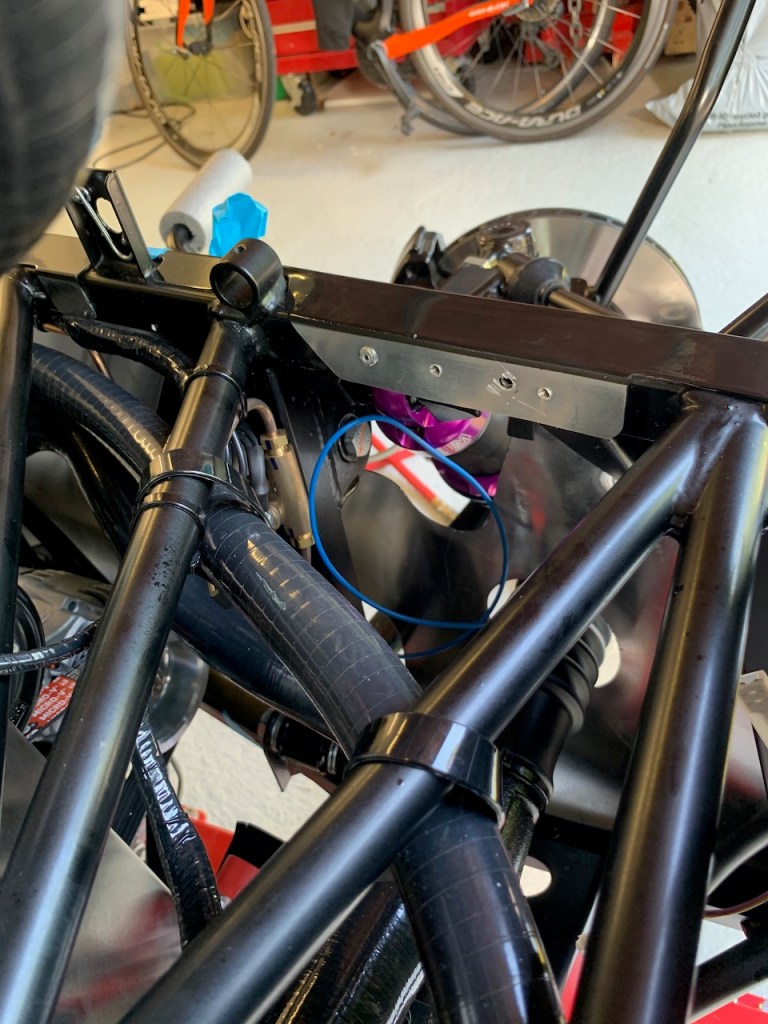
Not much to say about the rollbar other than the track-day roll bar uses 2 cap head bolts that come up from the top of the damper mount into the bottom of the rollbar and 2 hex head bolts that go through a plate on the top of rollbar down into the rear bulkhead. The last two bolts fasten the backstays to the chassis mounts in the boot.
The rollbar needs to be fitted before the rear dampers (otherwise you would need to remove the dampers to gain access to the mounting bolt).
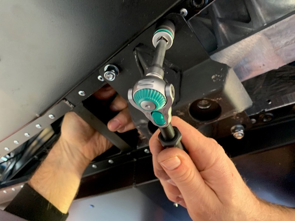
I’d heard stories of builders struggling to align the rollbar with the mounting holes but ours went in really smoothly.
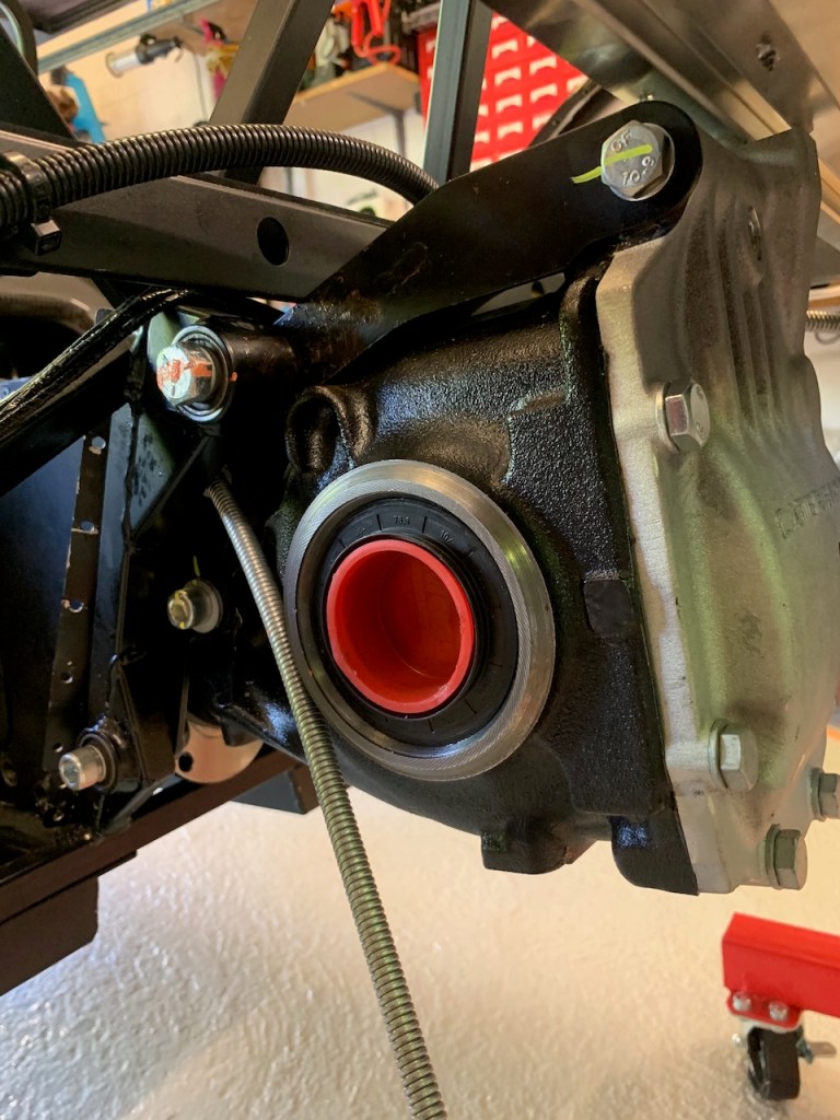
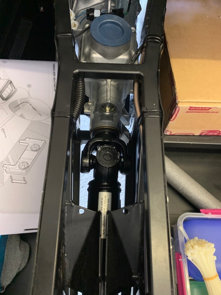
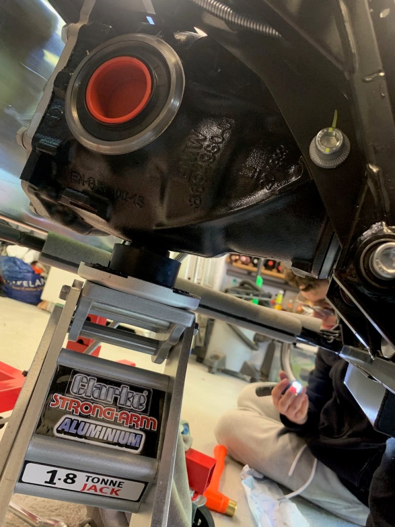
The first point is that the prop-shaft and handbrake need to be installed before attempting to fit the differential.
The second point is that the differential is very heavy and awkward to fit so two pairs of hands are really helpful.
Prop-shaft: The splined collar on the prop-shaft needs to be inserted into the gearbox. This requires manoeuvring the prop-shaft through the tunnel which is a tight fit at a point just behind the handbrake mounting bracket. The only way is to get it past is to make sure the flats of the UJ are aligned with the side of the tunnel and then give it a firm push. The splined collar needs to be inserted into the gearbox and mated with the output shaft. Once this is done the prop-shaft can be left alone until the differential has been fitted.
Hand-brake: The handbrake consists of the handbrake handle, the outer/inner cable, clevis, clevis pins, pulley, split pins and fasteners. In other words make sure you have all the pieces to hand before attempting the installation. The parts are spread across several bags and the split pins in particular are quite thin and easily mislaid (I found them in the miscellaneous fasteners bag).
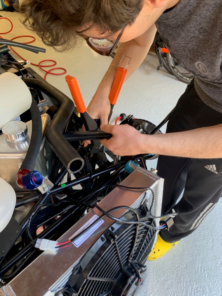
Differential: I do not have too many pictures of the installation because it was quite difficult and Michael and I literally had our hands full for most of it.
In theory it sounds simple: attach differential to the chassis with two bolts at the bottom and a long one at top using spacer washers to centralise. In practice the differential is a very heavy lump that needs to be precisely aligned to allow the tightly fitting bolts to pass through the bushings. In addition the differential must be evenly spaced in the chassis and there must be no gap between the chassis bushings and the differential cage. This requires the insertion of several washers of varying thicknesses in between the bushing and the cage. The washers come in 3 sizes: thick, thin and shim. I found that we could fit no more than 3 thick and one shim each side.
We made up the washer packs with the same spacing left and right / top and bottom. The difficulty is in inserting the washer pack into the tight gap between the bushing and the differential and then getting everything lined up accurately enough into order to get the bolt through. We started with the bottom bolts and used a combination of pin punches to align the washers and trolley jack to manoeuvre the differential into place. The bolts are also a very tight fit even when everything is aligned so plenty of copper grease and firm hits with the nylon dead blow hammer were necessary to drive them home.
We applied the same technique to the very long top bolt but in this case I ground a little more chamfer into to the tip of the bolt to help it through. The reason you have to insert the prop-shaft before beginning this part is that it is impossible to do it afterward and you do not want to take the diff off again once it is fitted. Similarly the handbrake cable runs either side of the diff and it would be impossible (or at least extremely difficult) to pass the through the locating brackets with the diff in situ.
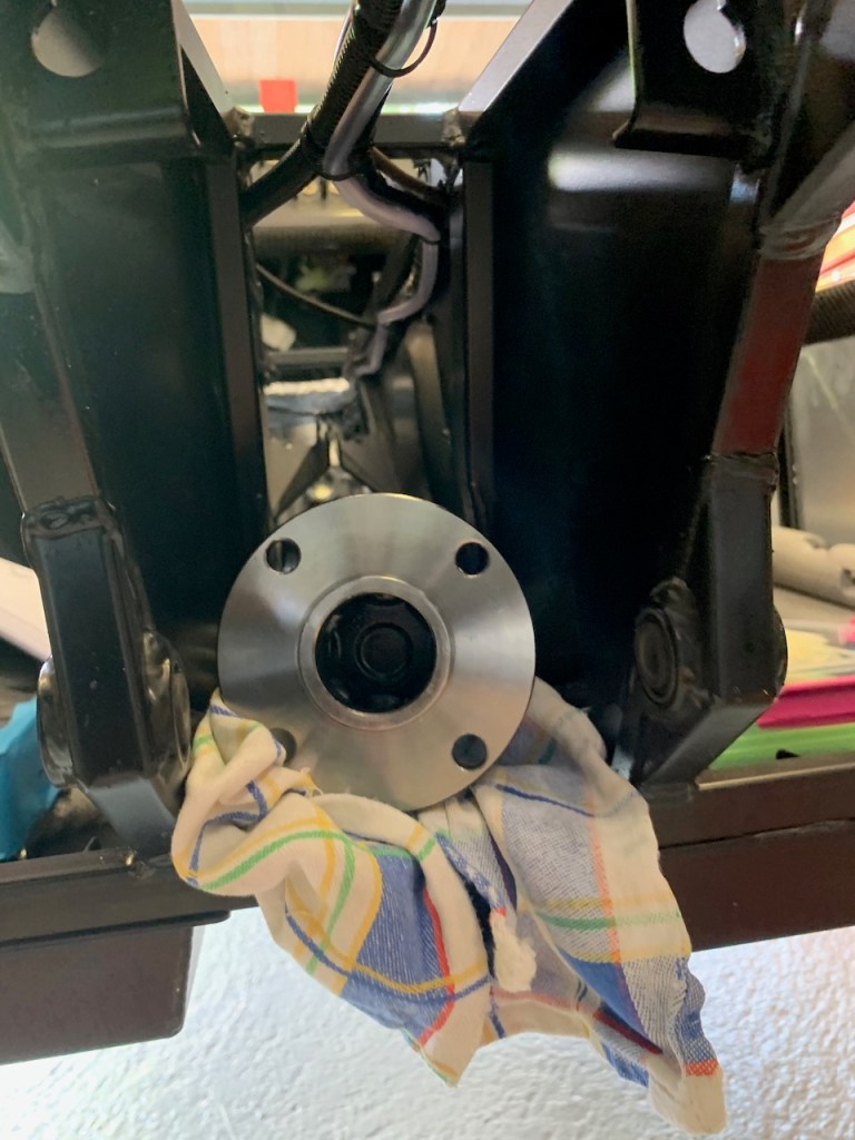
The last job was to attach the propshaft to the differential using the four cap-head bolts. We threadlocked the bolts and then torqued them up.
The whole process of fitting the differential took all afternoon.
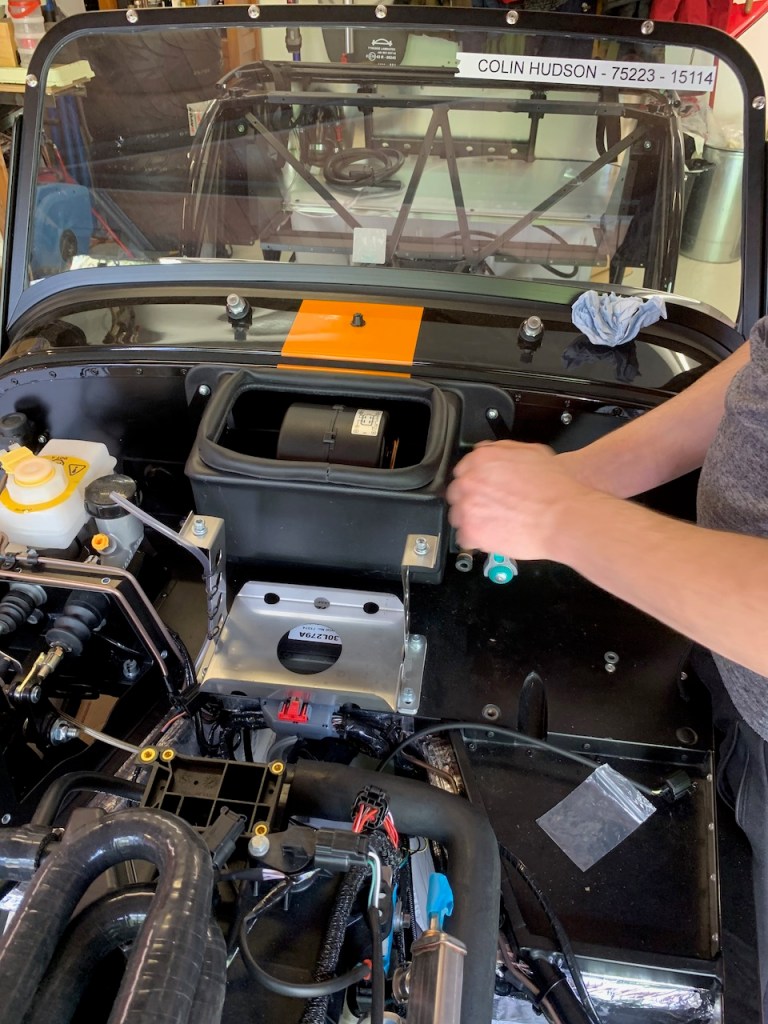
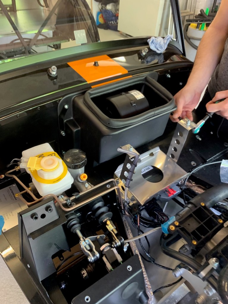
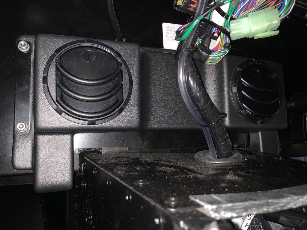
Installing the heater starts by separating the vent panel from the heater box. The vent panel goes inside (‘ears’ pointing down), the power cable is routed through the scuttle (this requires a grommet to be split, passed over the cable and then glued back together). The two parts are simply bolted together and the heater cable connected to the wiring loom under the dash panel.
Next up is the heater control valve and cable. The heater control is a simple push / pull device just above the driver’s right knee. As other builders have noted the hole in the scuttle needed enlarging in order for the cable to pass through.
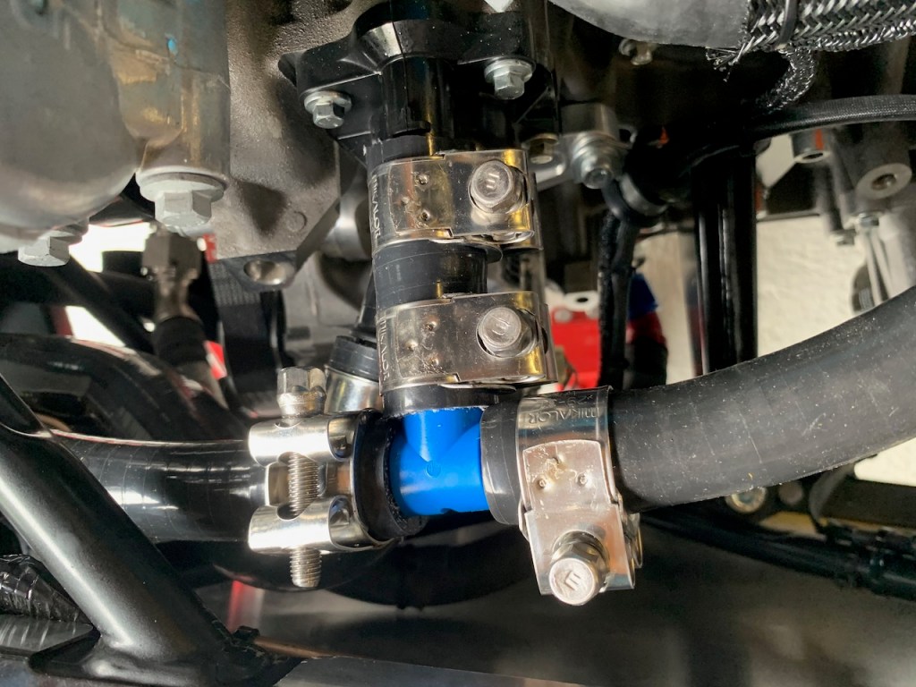
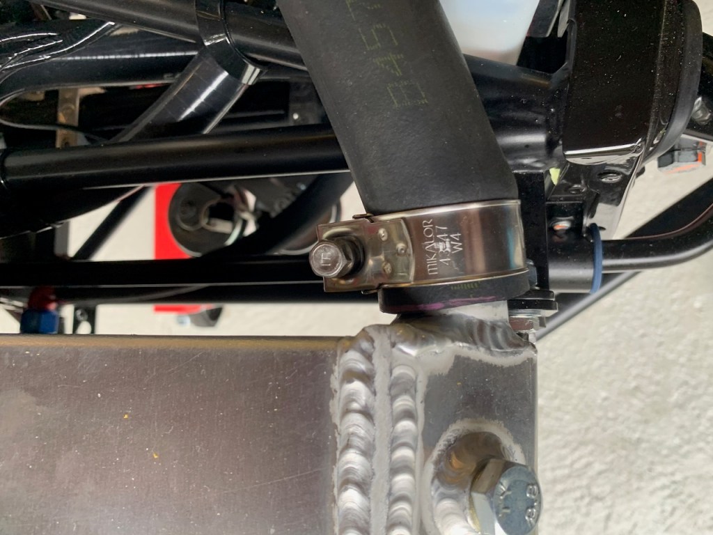
Connecting everything up involves cutting hoses and joining the pieces together as per the build manual although I chose to use Mikalor stainless steel hose clamps as they look neater and give a more even compression than the supplied jubilee clips.
The all important ‘submarine’ with its temperature sensor is installed at the rear of the engine and is connected with the green wire to the temperature sensor and an earth wire to the boss on the body of the ‘submarine’.
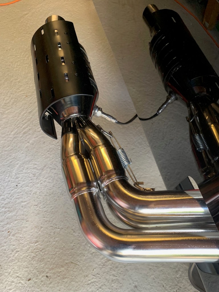
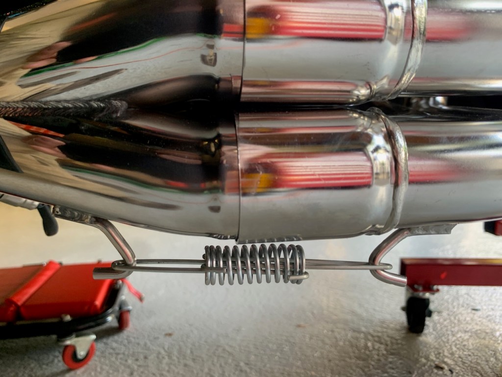
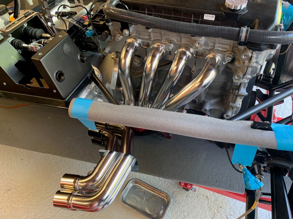
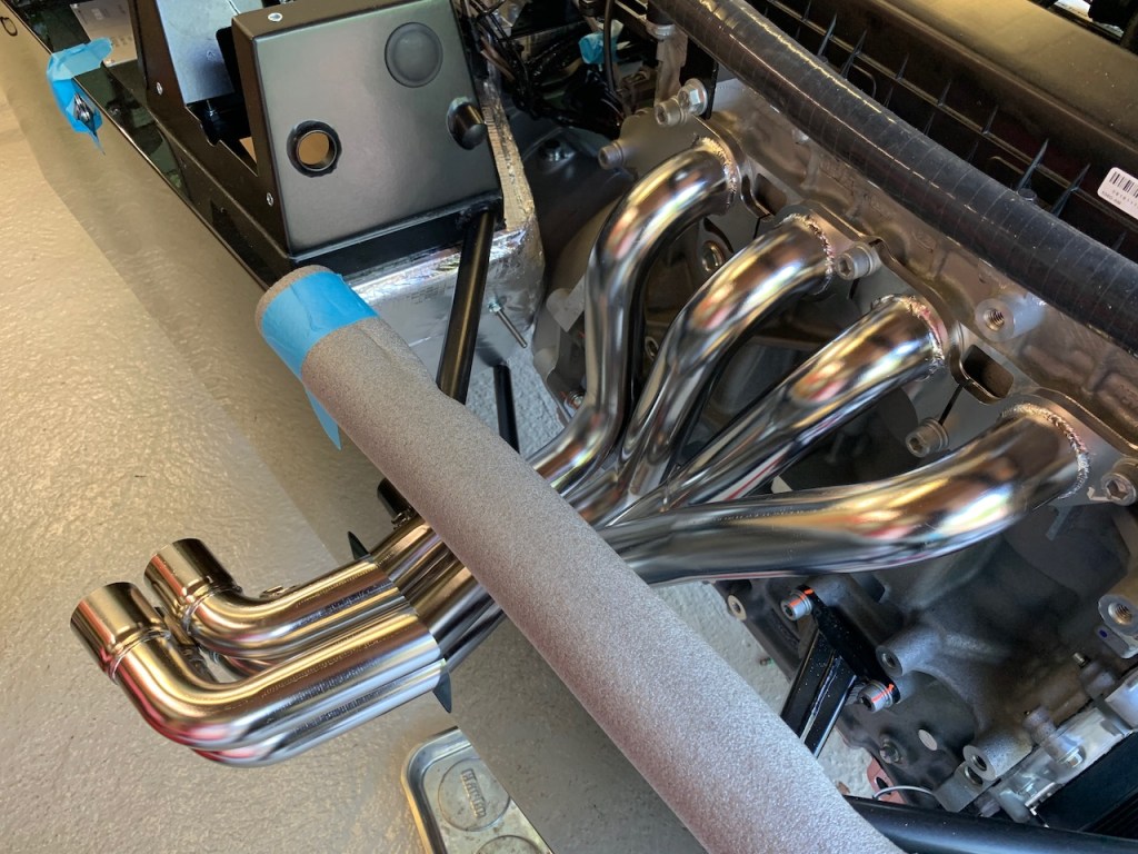
The collector and catalyst are one unit and are a push fit over the ends of the four primaries. I found it helped to loosen the primary bolts slightly to give a little play in the tubes and help line everything up to the collector.
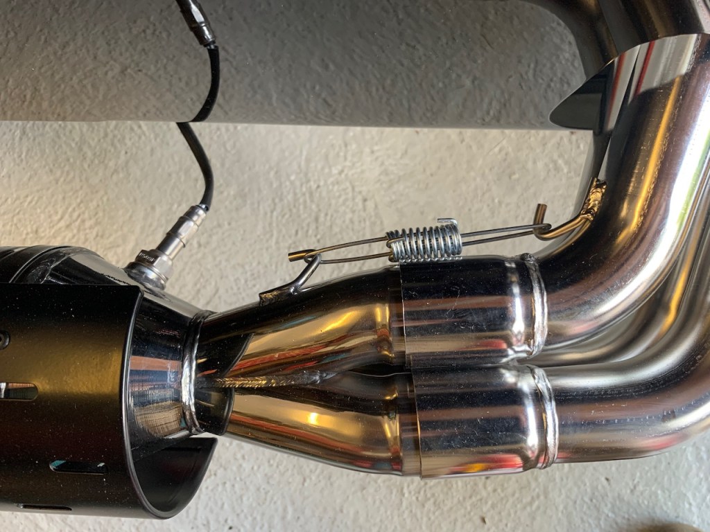
The collector is held on by two compression spring and hook assemblies that act as a tension fitting to pull the two parts of the exhaust system together.
Two bent pieces of wire with hooks on the end pass in opposite directions through the compression spring and the wire loops at each end need to be slid over the hooks on the primary and collector.
The spring must be compressed to give enough reach to get over the ends of the exhaust hooks. The recommended ‘cable-tie method’ is well documented on other blogs and involves compressing the spring in a vice and using 3 or 4 cable ties to hold it fully compressed whilst the whole lot is slid over the exhaust hooks. Once in place the cable ties are cut and the tension pulls the primary and collector together. The last job at this point was to torque up the primary gasket / exhaust manifold bolts to 34Nm.
Note that I installed the lambda sensor into the collector before fitting to the primaries to avoid any risk of slipping with a spanner and damaging the bodywork.
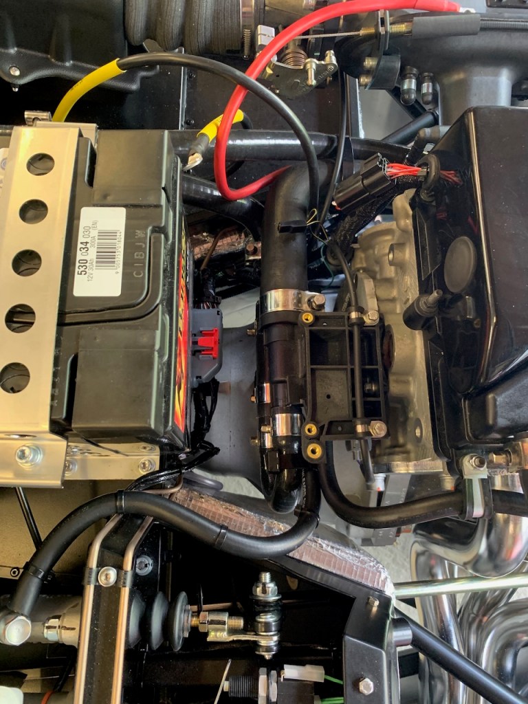
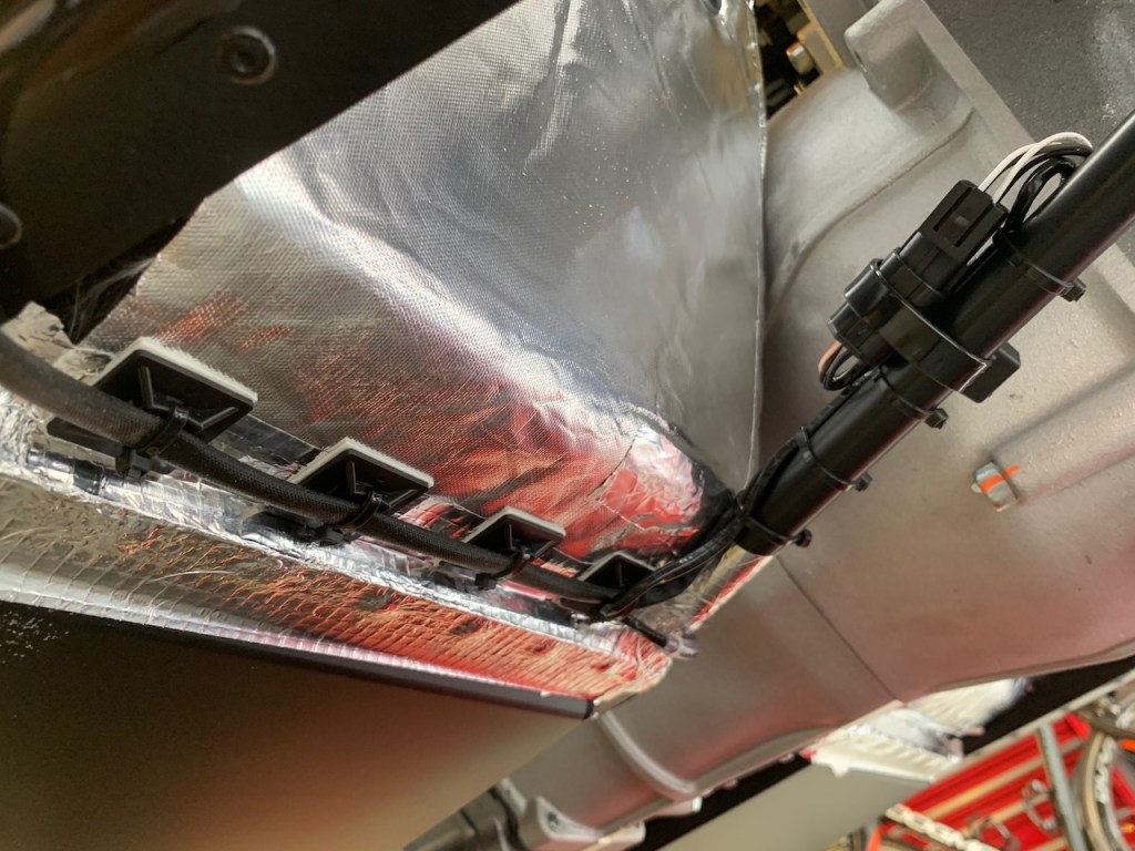
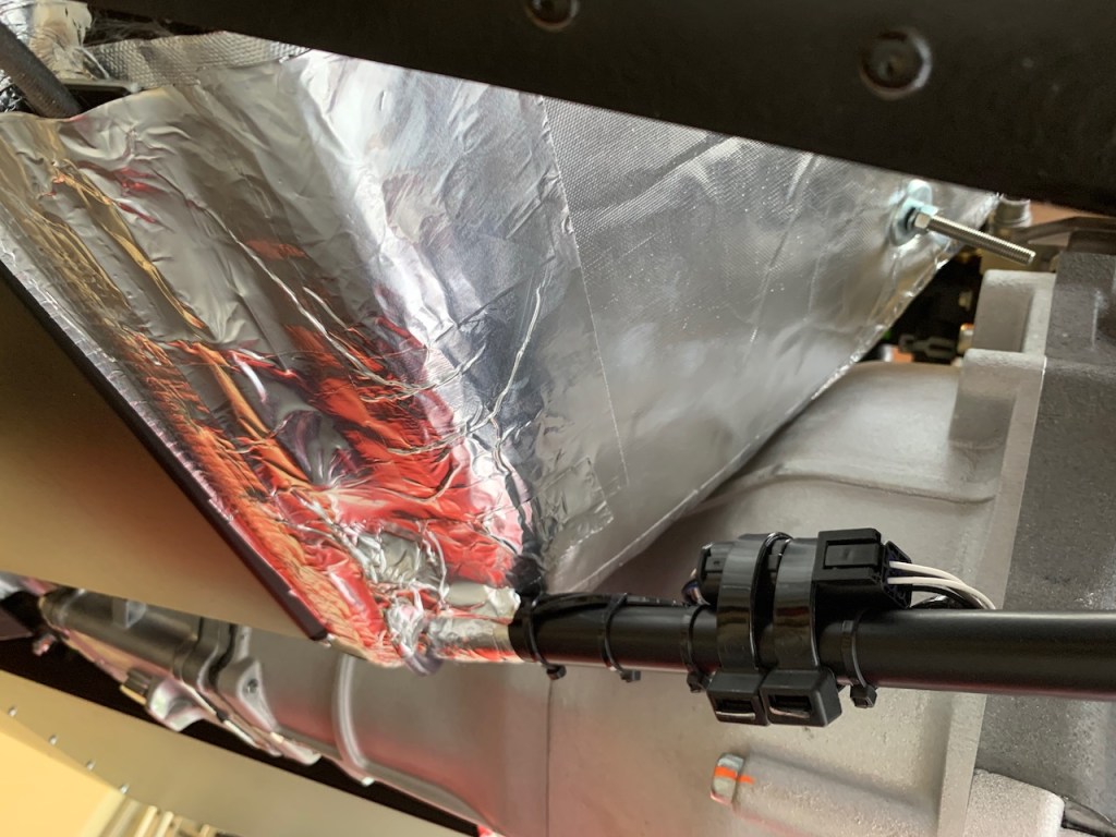
The lambda sensor needs to be connected to the wiring loom and the wiring secured to the chassis. I stuck cable tie blocks with 3M self adhesive pads to the heat shield along the chassis rail and then tidied everything up with more cable ties before covering it all with aluminium tape. I even used a small section of washer pipe to protect the loom cable as it passed around the bottom edge of the footwell. There is a lot of surplus cable to get rid of so I doubled this back on itself and secured it with the Econoseal connector to the chassis rail with cable ties.
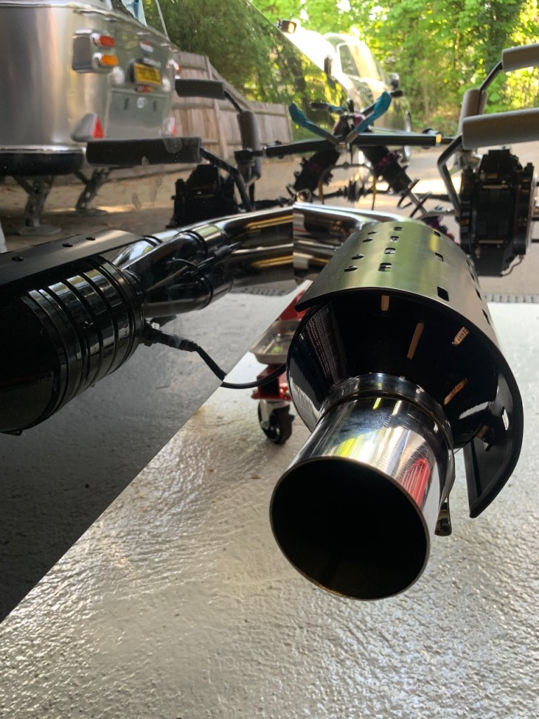
The last job was to fit the black heat shield which is secured to the catalyst with two very large jubilee clips.
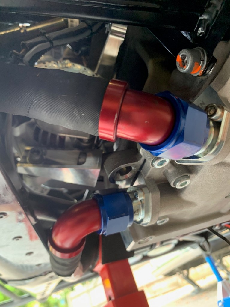
Oil cooler hoses: The oil cooler hoses are difficult to fit, there is not much room in the engine bay and the hoses themselves are quite inflexible. The new manual tells you which is which but finding a route through the maze of pipes whilst keeping clear of the rotating belts and pulleys at the front of the engine is difficult.
The oil cooler fittings are the ‘Dash-‘ type that use a 37 degree flare on the fitting and the inverse 37 degree flare on the tube to form a metal to metal seal. The fittings are aluminium so great care must be taken not to cross thread. The best way to fit them is to use plenty of copper slip on the threads and carefully hand tighten until resistance is felt and then use a large spanner to nip them up with a final 1/8 turn.
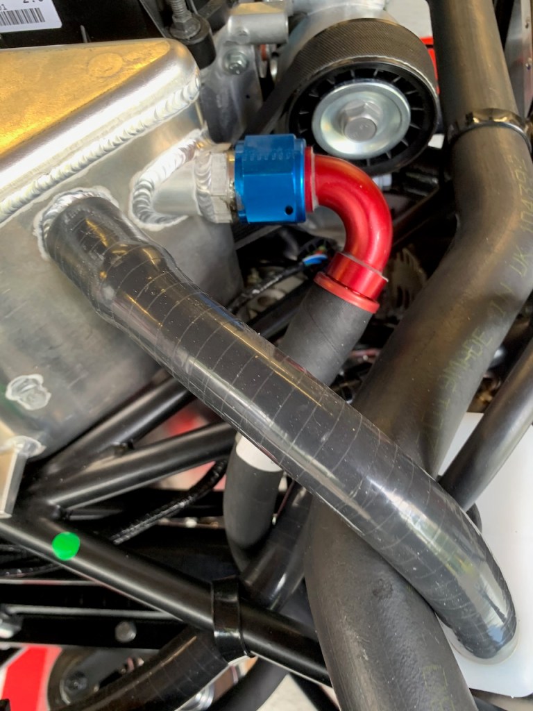
Although everything is connected and I’ve avoided moving parts I am still not sure I have the optimal routing between the chassis members (email sent to Caterham for some advice).
The pipe exiting the front of the oil cooler plate is clear of the chassis but runs close to the 90 degree corner of the rear wishbone bracket – I think I will take a file to radius this corner and then glue some IVA trim to the edge for piece of mind.
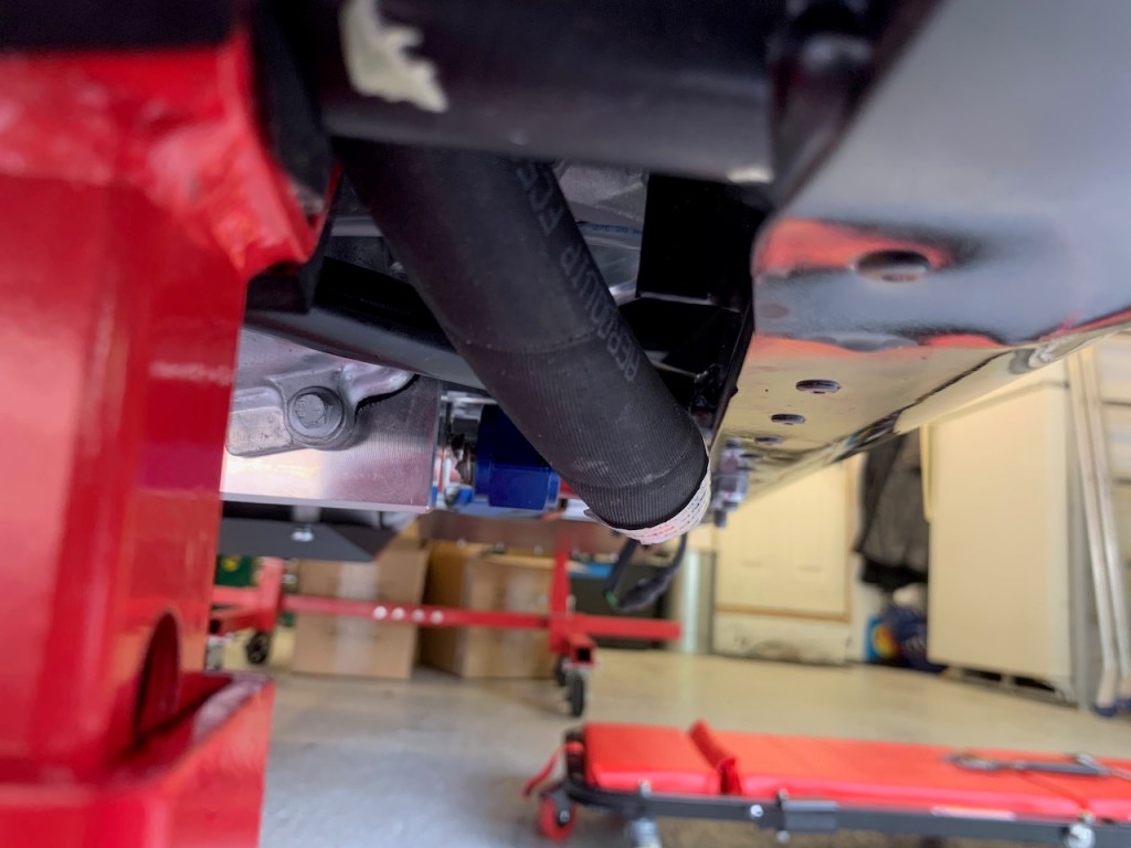
The pipe exiting the rear of the oil cooler plate goes up inside the engine bay between a diagonal chassis member and the side skin. Whilst this is clear of the alternator pulley / belt it does run close to the chassis. To avoid the risk of chaffing I’ve used a piece of split / cable tied radiator hose as a conduit over the bottom chassis rail and will use some thinner tubing (or possibly a section of bicycle tyre and cable ties) to protect the hose where it rests against the diagonal chassis member.
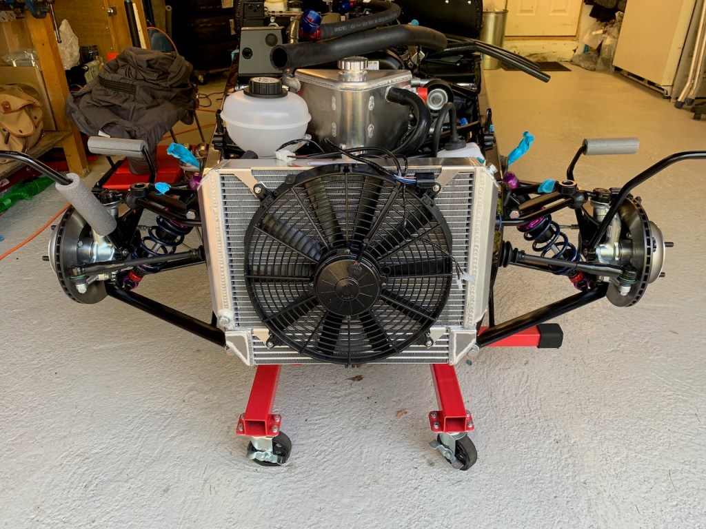
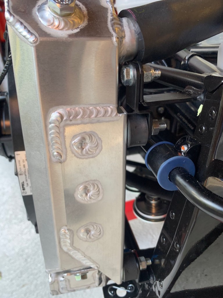
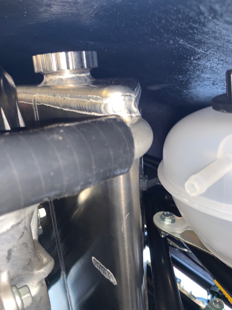
The aluminium radiator and oil cooler are a combined unit and come pre-assembled and very carefully packaged. Installation requires four rubber bobbins and two lowering brackets. The lowering brackets fit on the top chassis mounts and ensure the mounting points all line up. It is a simple job to fasten everything together.
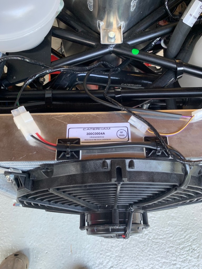
Radiator Fan: The radiator fan is supplied separately and again is easy to install onto the front of the radiator. There are only two points to note:
The flat edges must align with the top and bottom of the radiator
The four plastic fan mounts (found in the ‘cooling pack’) must be pushed into fan itself before installation – these required a little persuasion with my nylon deadblow hammer and some silicone lubricant
We are in week 3 of the Coronavirus lockdown and it is Easter Weekend, the weather is nice for once but we are all confined to our homes. This is an opportunity to crack on with the build and so we got on with the installation of the dry-sump, expansion and breather tanks.
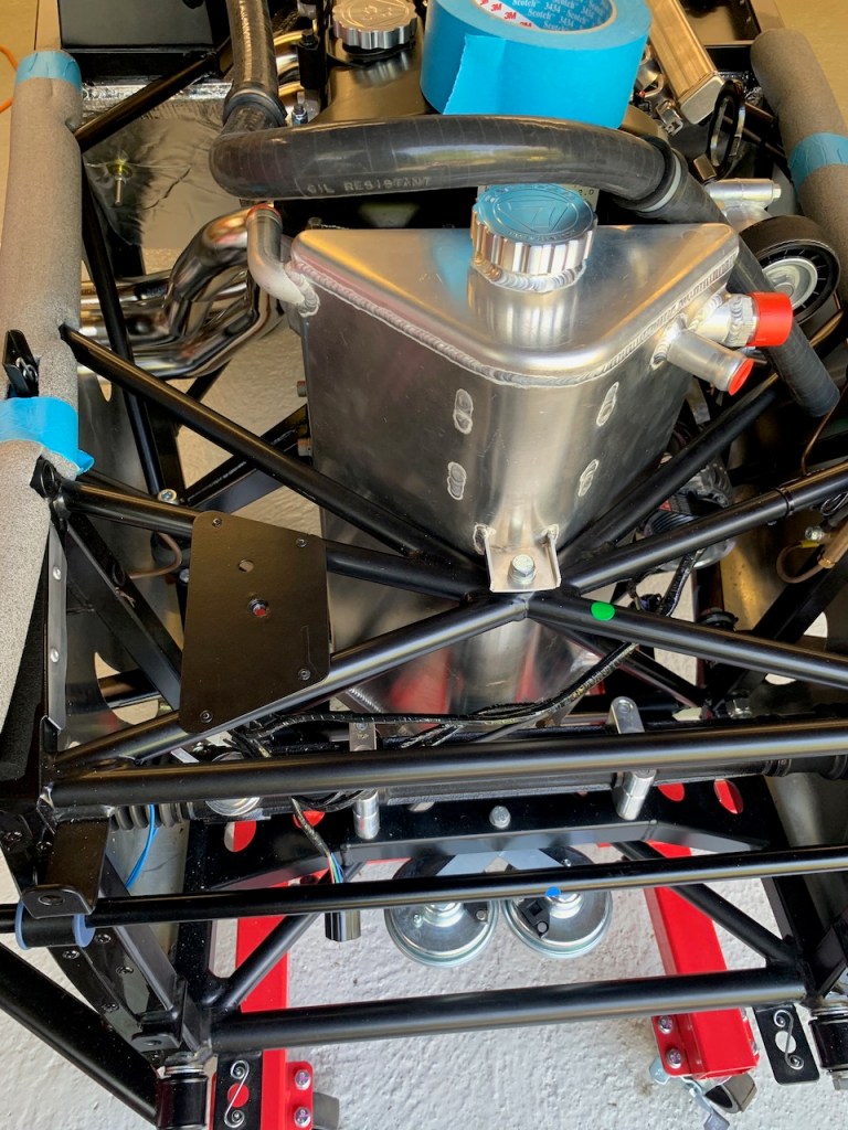
Dry Sump Tank: This is a rather large triangular stainless steel tank that fits in front of the engine. It is shaped to fit into ‘V’ of the cross-brace and is fastened with two P-clips at the bottom and a set-screw and spacer washers at the top. The chassis is already drilled and tapped at the top mount and apart from moving part of the wiring loom out of the way went in without a problem. It is important to remember to fit the temperature sender in bottom of the tank with PTFE tape to avoid any leaks. Whilst there is no separate oil temperature guage there is provision in the loom for the sender and a switch can be fitted to toggle the water temperature guage between oil temperature and water temperature if so desired.
UPDATE: Although the oil tank has a dipstick the nose cone has to be removed to use it which is a little inconvenient and checking the oil is probably the single most important precaution against engine wear. I will have this modified to install a sight tube in the rear of the tank so the oil level can be visually checked just by removing the bonnet. The tank will also be anodised black for cosmetic reasons.
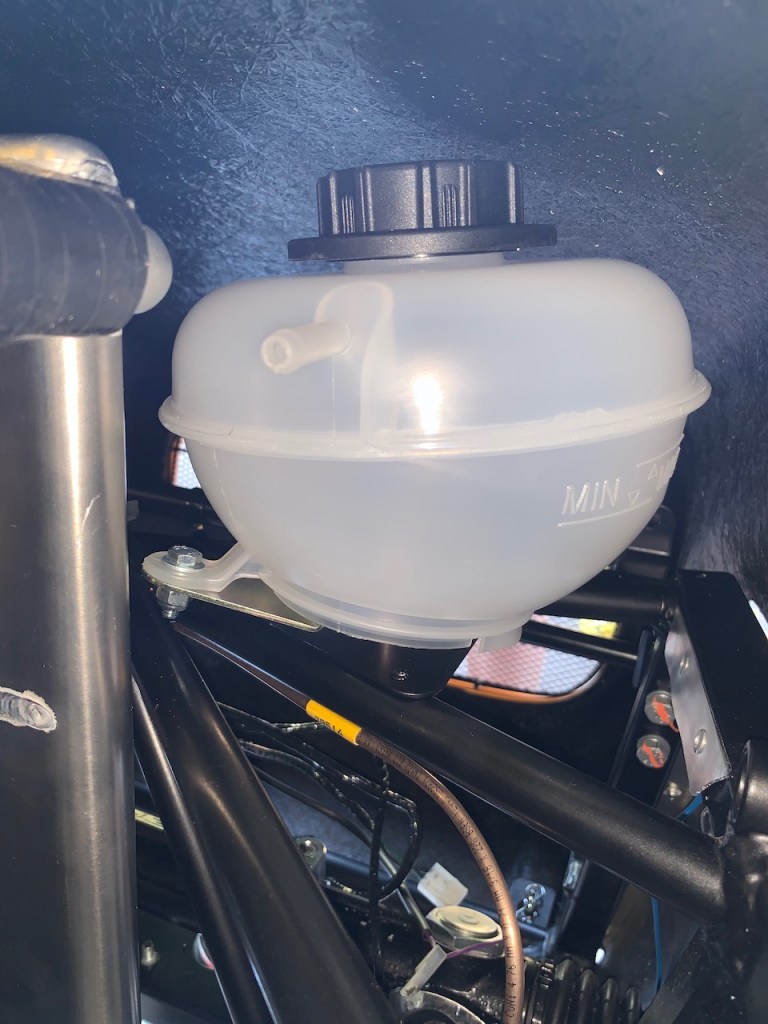
Expansion Tank: The coolant expansion tank fits onto the front right hand side of the chassis just in front of the dry-sump tank. A chassis mounting plate needs to be riveted to the cross brace which requires four holes to be drilled. Thankfully this part went without too much drama and we got all the rivets in (it is difficult to drill 4 accurately spaced holes into round tubing but after a lot of measuring we ended up not perfect but close enough that all the rivets engaged properly). The expansion tank has its own mounting plate which is bolted to the chassis plate. The expansion tank mounting plate needed a bit of work with a Dremel and carbide burr to get the bolt to pass through.
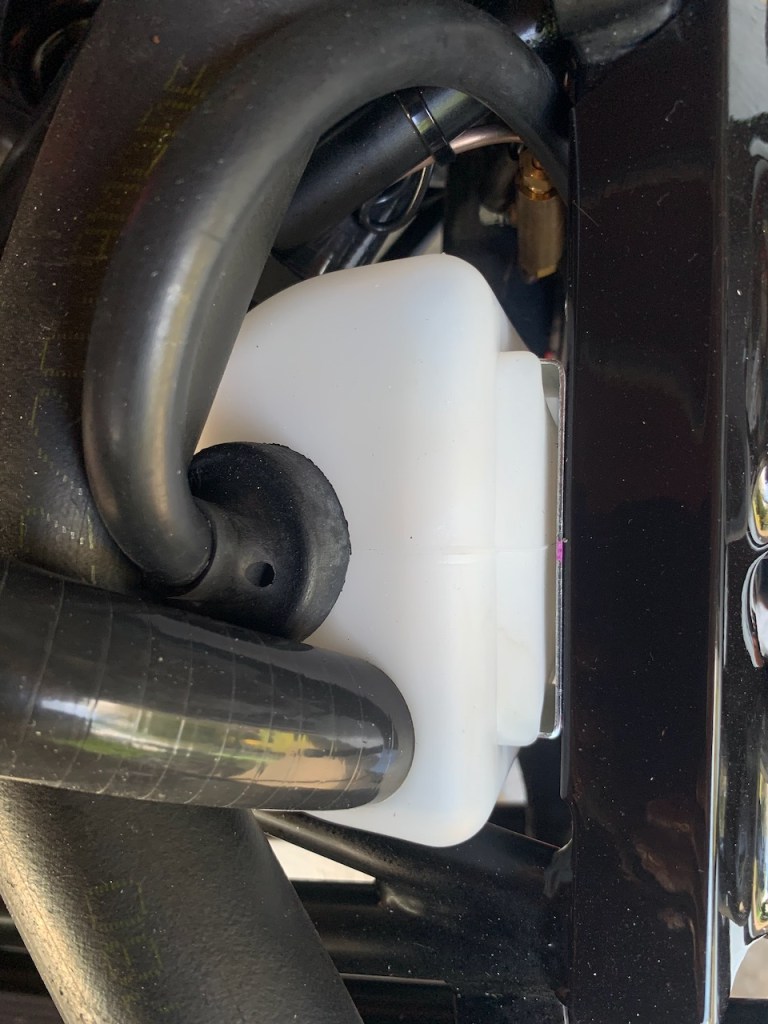
Breather Bottle: The oil breather tank is located on the left hand side of the chassis in front of the damper mount. The mounting plate for the breather bottle needs to be riveted to the chassis rail and this requires a rivet to be drilled out and two new holes drilled. I used the air powered angle drill for this as it is the smallest drill I have. The breather bottle needs to have a hole drilled into its top corner in order to accept the breather hose from the oil take – I used a step drill bit for this to give a clean finish.
This gave us an opportunity to trial fit the nose-cone to check for clearances – all OK.
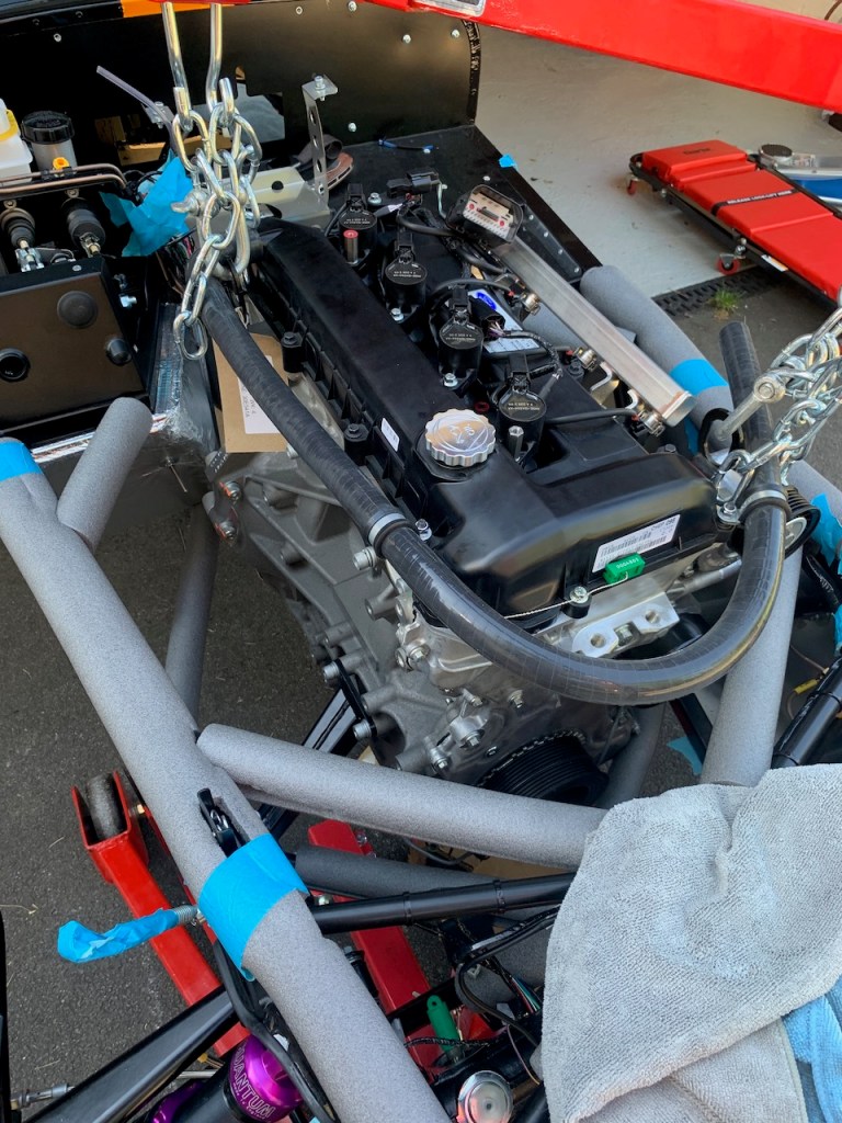
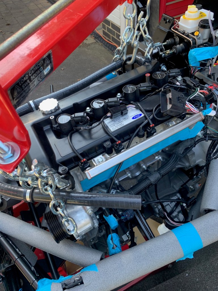
Now that the engine and gearbox are in it is time to fit the primaries but before that the alternator and starter motor need to be re-installed.
Starter Motor: Very easy, goes straight in with two cap-head bolts
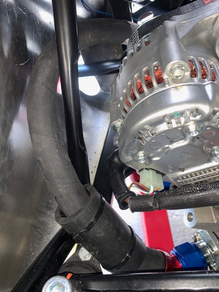
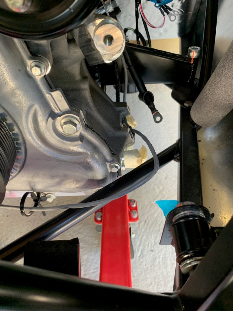
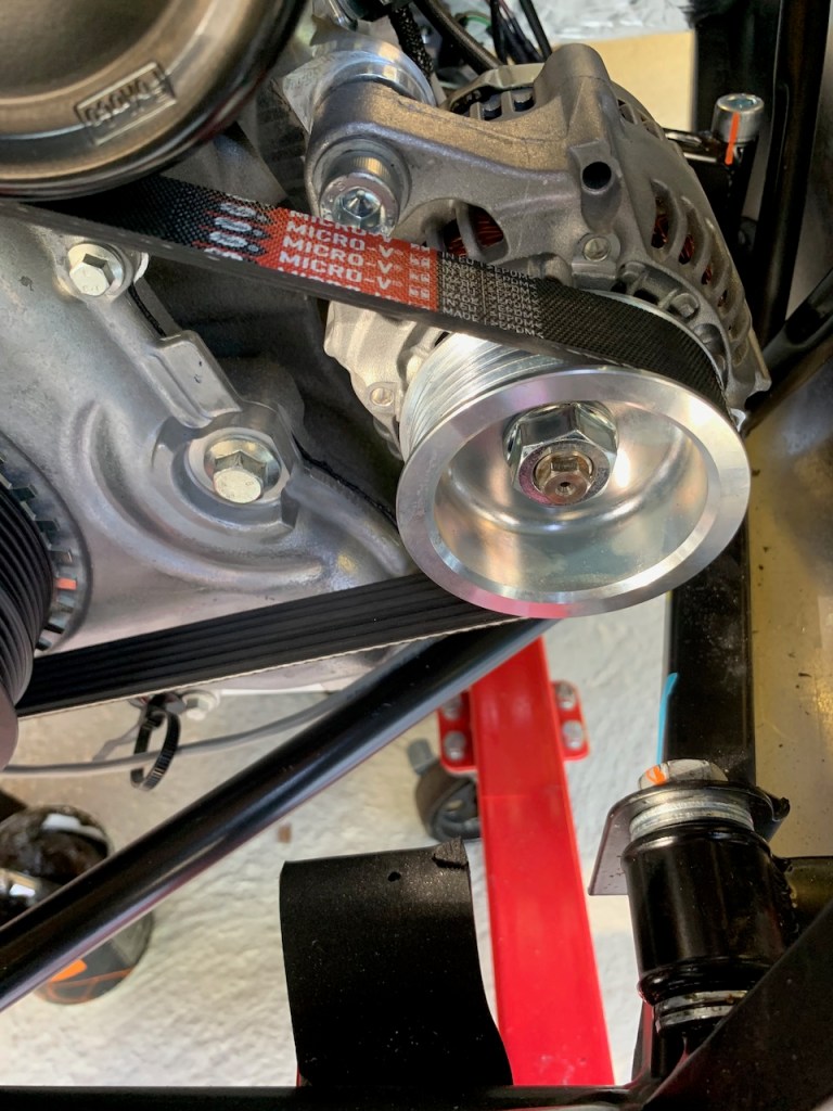
Alternator: This was a lot harder since there is not much room in the engine bay. After a couple of attempts I found the best method was to detach the lower alternator mount from the alternator and loosely attach it to the engine block first. The top bolt for the alternator is next and loosely fitted to give some wiggle room. The bottom bolt for the alternator can now be started and the whole lot gradually tightened up, starting with the bottom alternator mounting bracket bolt as this is the hardest to reach. After 30 minutes of gradual tightening the bottom bolt and bracket were fixed in place leaving an easy job of tightening the top bolt.
Plenum chamber: The plenum chamber / throttle body assembly was removed as part of the preparations for installing the engine. This will be left off until all the engine bay plumbing is finished.
Primaries: Installation of the exhaust primaries begins with the removal of the gasket and masking tape used to seal the exhaust ports.
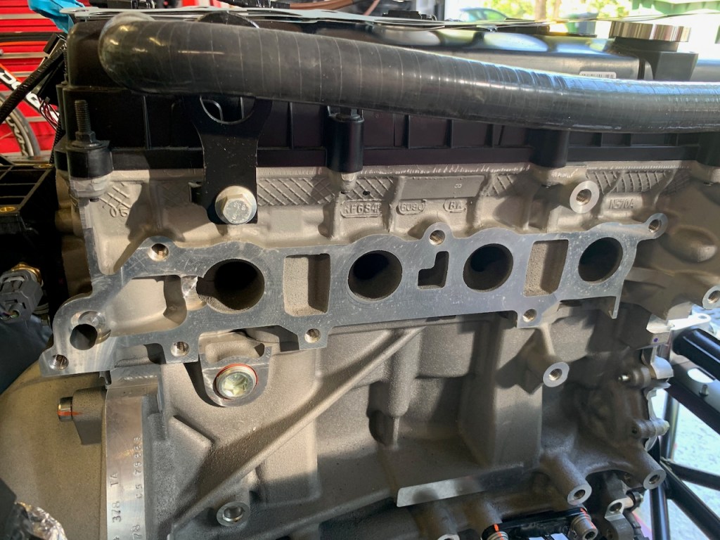
It is important that the primaries are installed before the dry sump tank is fitted as you will need the space in order to manouvre primary #4 into position.
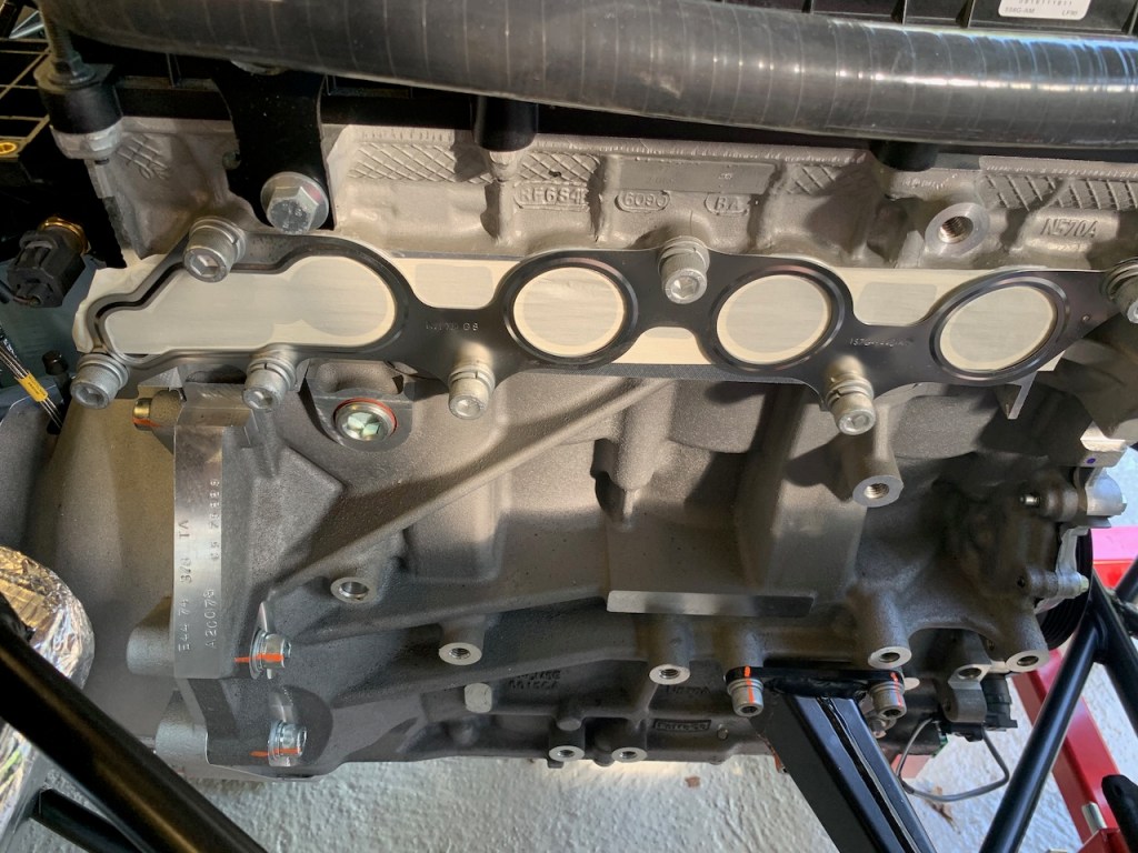
There are four primaries and the recommended installation sequence is from rear to front. Before starting I used some auto masking tape to protect the hole in body skin. Starting from within the engine bay each primary is rotated and manouvered into place taking care not to ding anything in the process. Obviously the steel gasket must be fitted between the primaries and the engine block but as this is one piece it is easily held in place by primary #1 bolts. The bolts are left finger tight for the moment and will be torqued up when I fit the collector as a bit of wiggle room will be necessary at that stage.
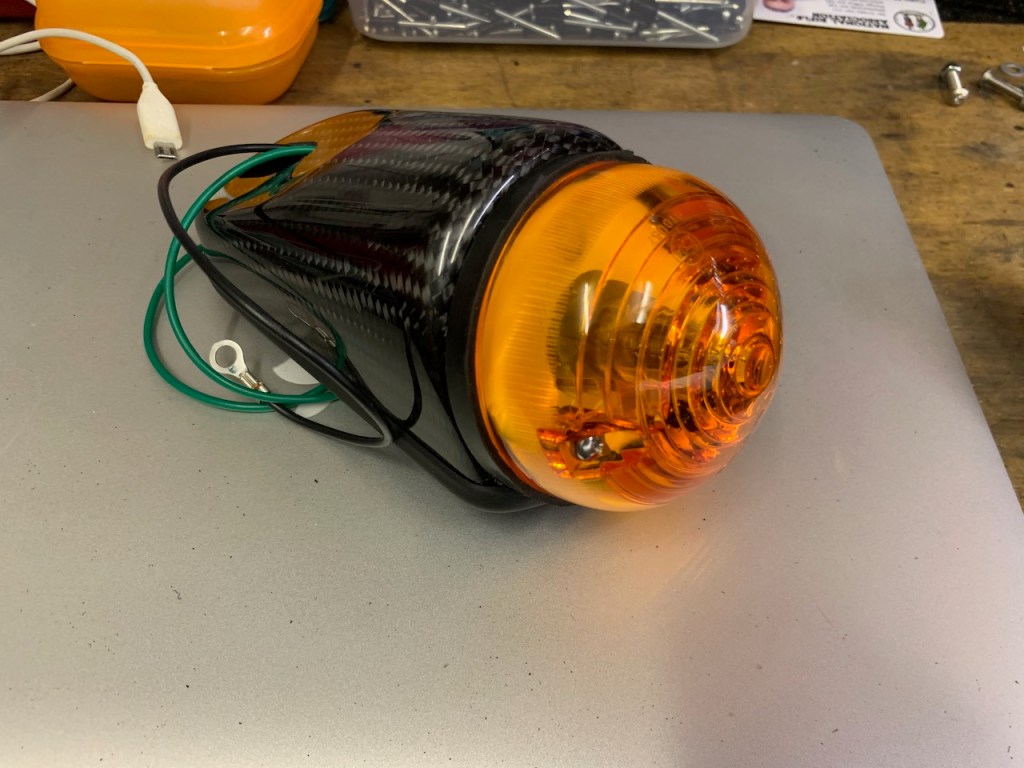
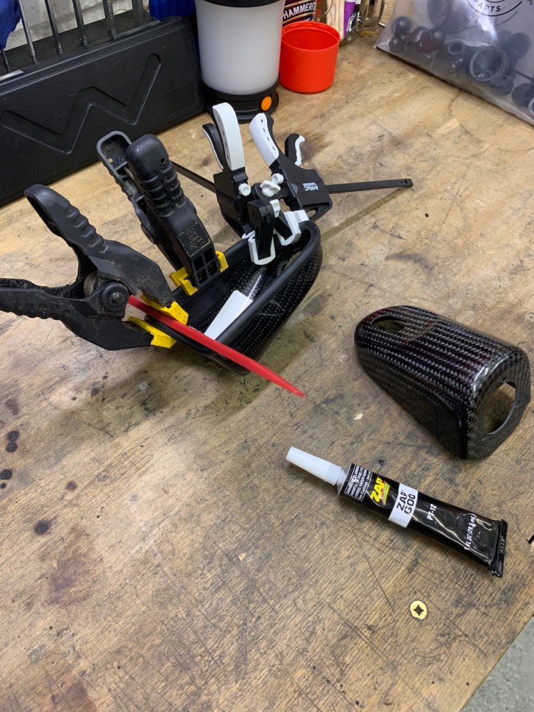
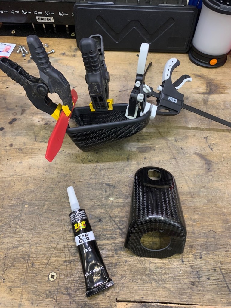
The indicator pods need to have IVA trim applied all round their edges. I also understand that orange lenses with conventional bulbs need to be fitted for the IVA test.
The rubber IVA trim needs to be glued in and I used a selection of clamps to hold it in place around the tight radiuses.
I let the glue / clamps do their work overnight before fixing the lens holder in place. I used stainless button head set screws and nyloc nuts instead of self-tapping screws as the carbon fibre the pods are made from is very thin (and light).
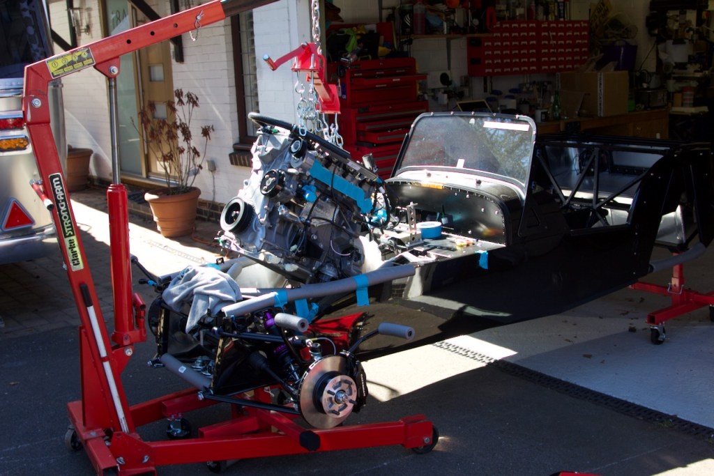
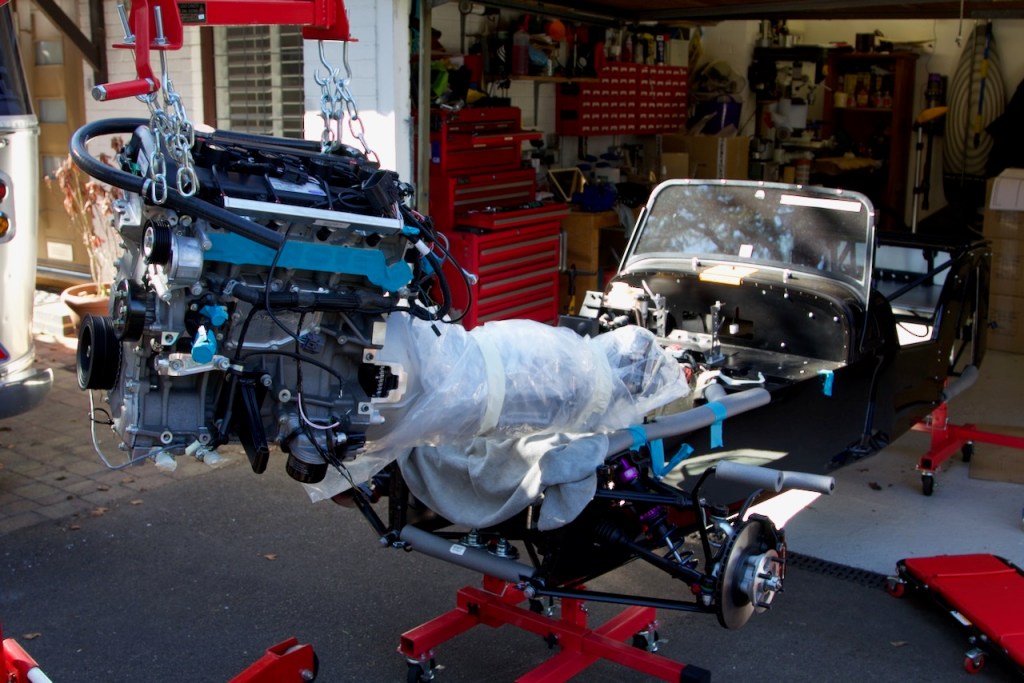
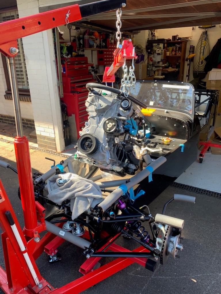
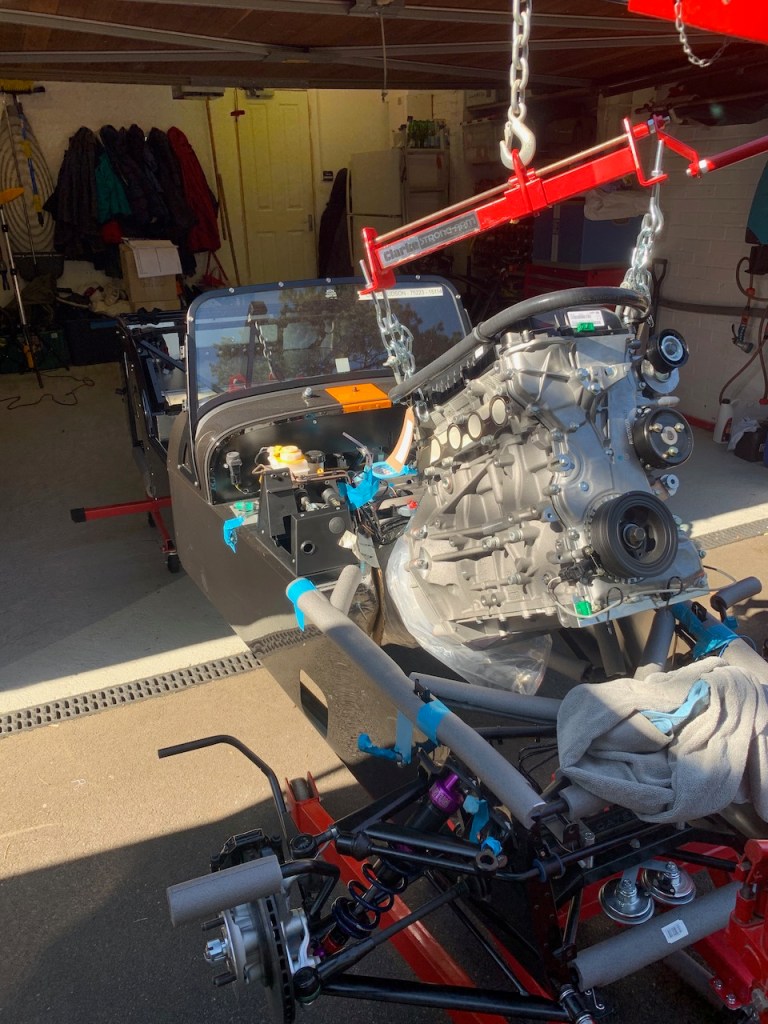
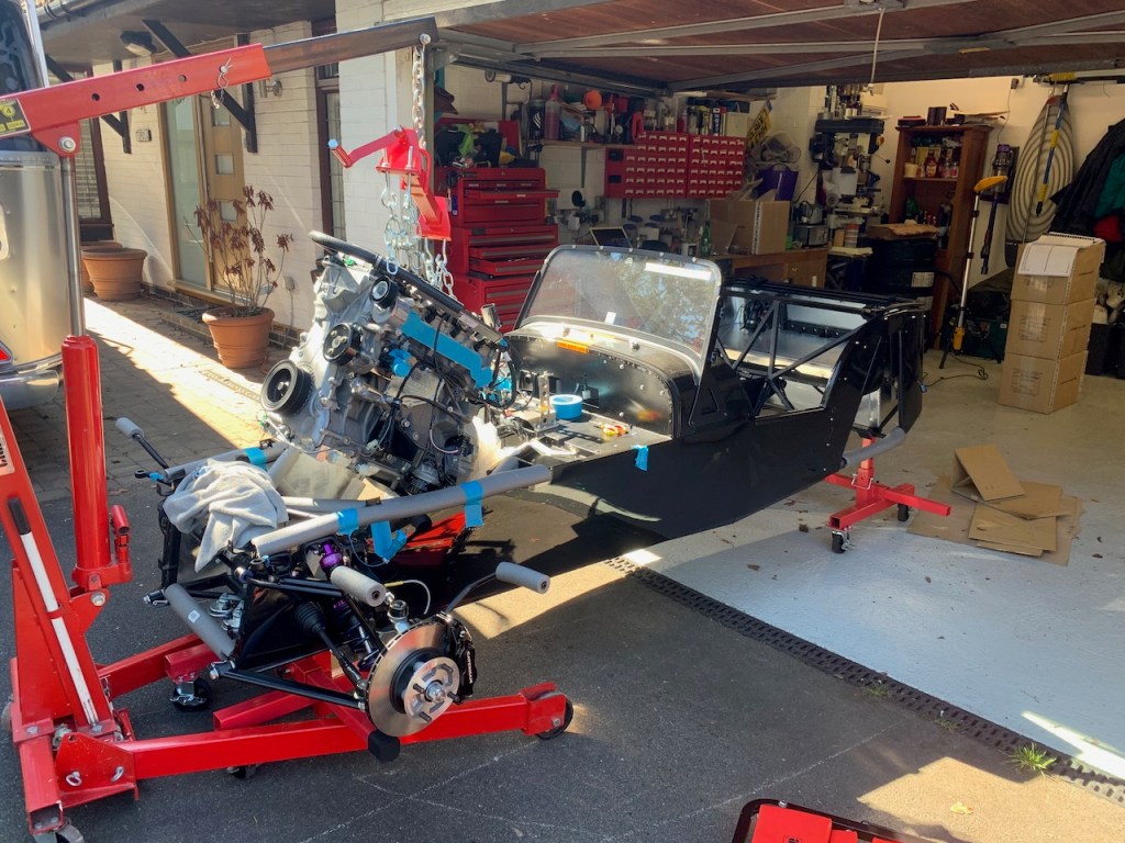
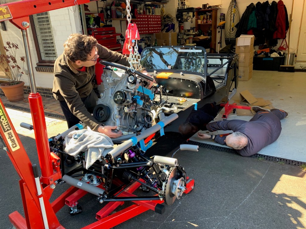
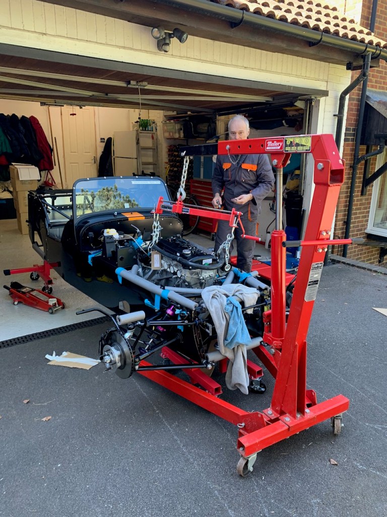
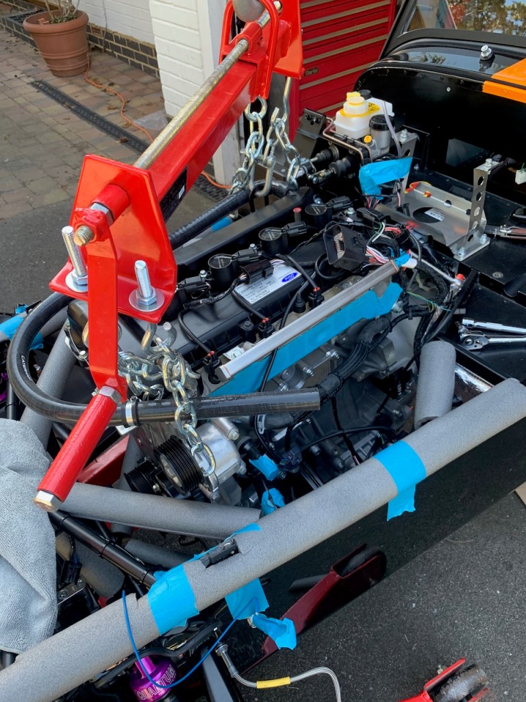
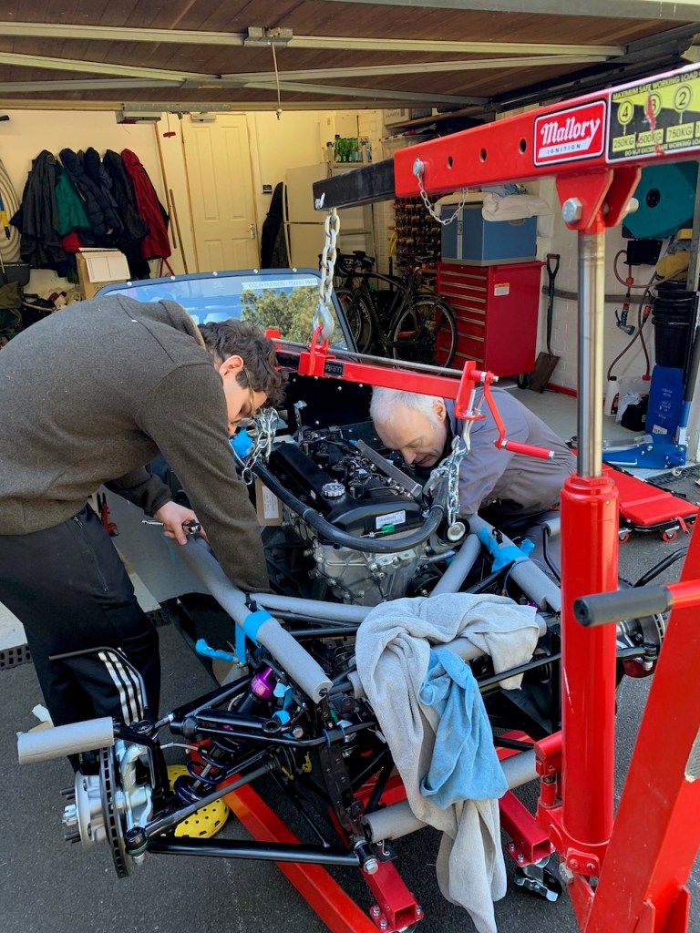
The engine installation took place without any drama. Luckily the weather was perfect so we pulled the engine crane with suspended engine & gearbox onto the drive and rolled the car forward on its mobile axle stands.
The mobile axle stands definitely come into their own for this part of the build but there are a couple of points to pay attention too. First of all the front of the car should be lowered as this improves clearance and secondly the front axle stand struts need to be as close together as possible to allow the car to move close to the engine crane (if the struts are two far apart the stands will foul the legs of the engine crane). It is also worth noting that we had the engine crane on full extension where it is rated to handle 250Kg (I understand the engine + gearbox to be around 180Kg so this is well within capacity).
We also protected the chassis with foam pipe lagging and wrapped the gearbox in the plastic bag it came in as it is a really tight fit in the transmission tunnnel and very easy for a sharp edge to tear the heat insulation.
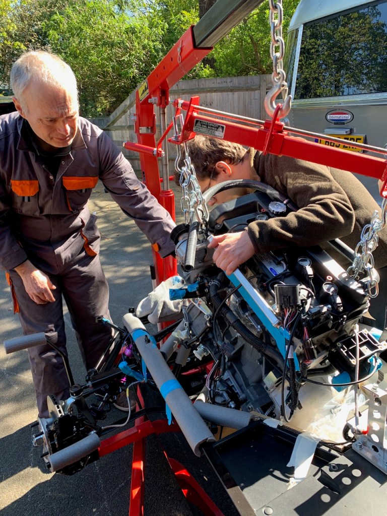
The installation itself is all about moving in small steps, either height, reach or angle, taking care at all times that the engine does not foul the chassis and most importantly does not trap any fingers as it is gradually lowered into place.
Gearbox wrapped
Some adjustment of the hoist straps removed a lot of the tilt
First stage quite easy
Millimeter by millimeter from this point
Load leveller proving really useful
Checking gear box clearance
Clearing the front chassis members…just
Almost there
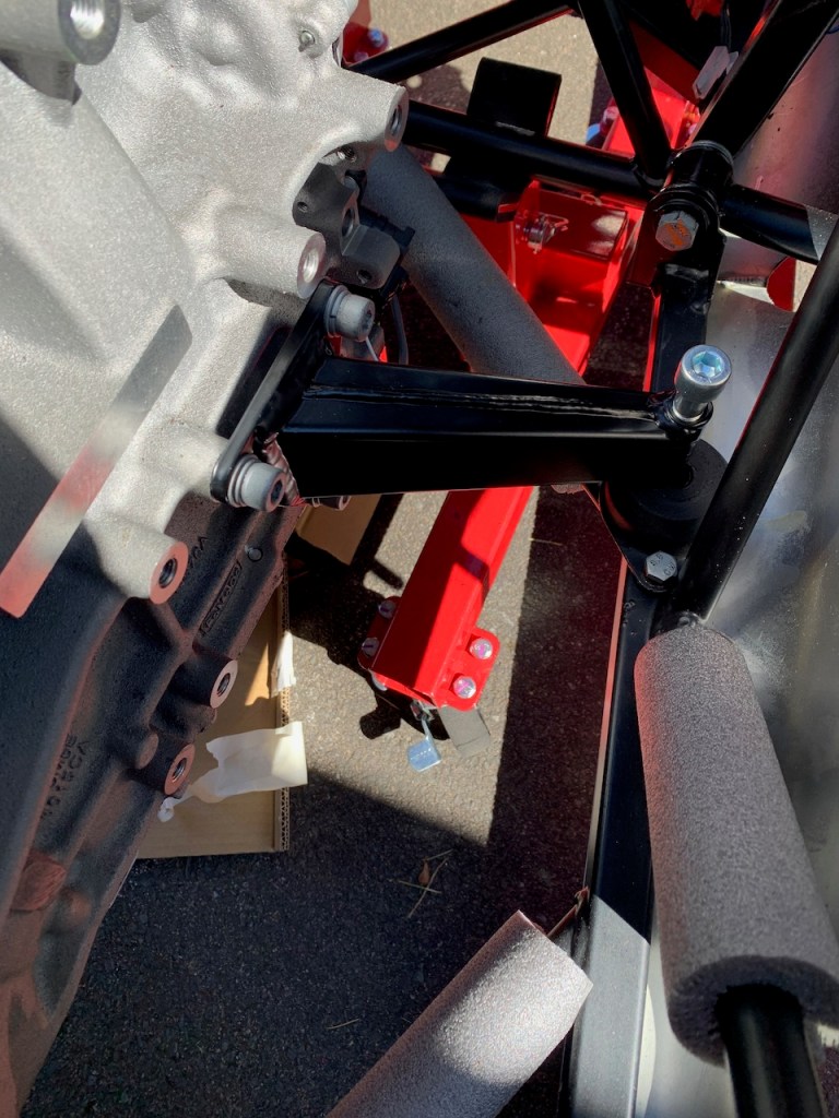
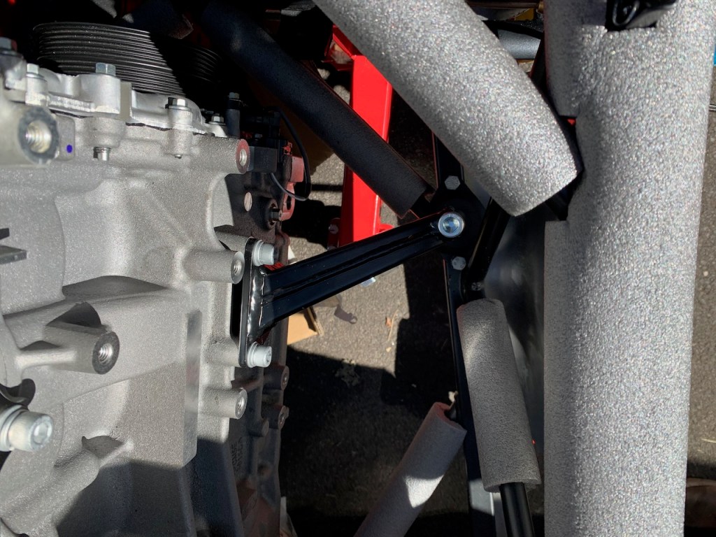
Fitted the engine mounts at this stage
on both sides
Checking clearances in the engine bay
It is a tight fit
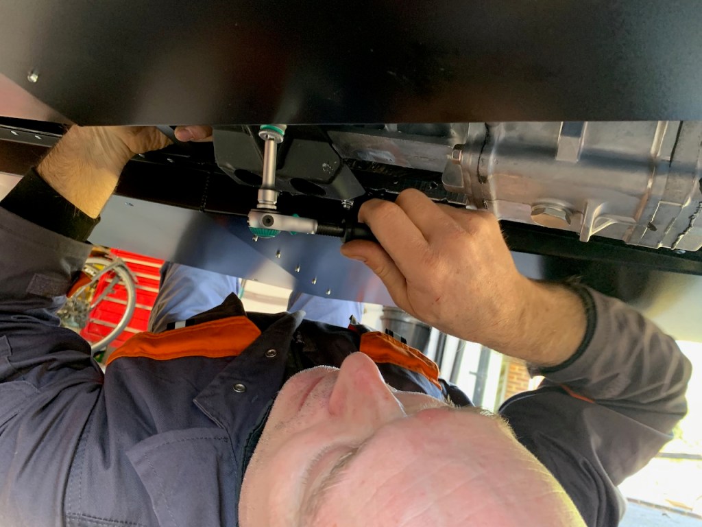
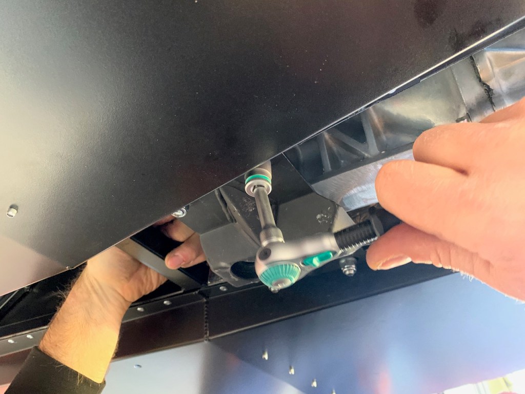
Trolley jack used to help the gearbox clear a chassis member