There are a few jobs to do to prepare the engine for installation, none of them are particularly difficult so most of the this post will be told using pictures.
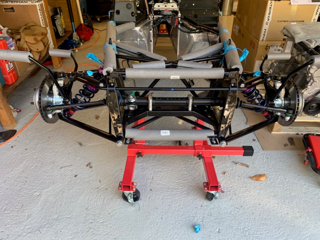
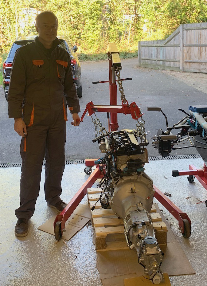
It is worth mentioning that an engine crane is essential and a load leveller is highly recommended. I have an engine crane from the GD427 build but decided to buy a load leveller for this installation as the clearances are really tight.

Start by removing the starter motor 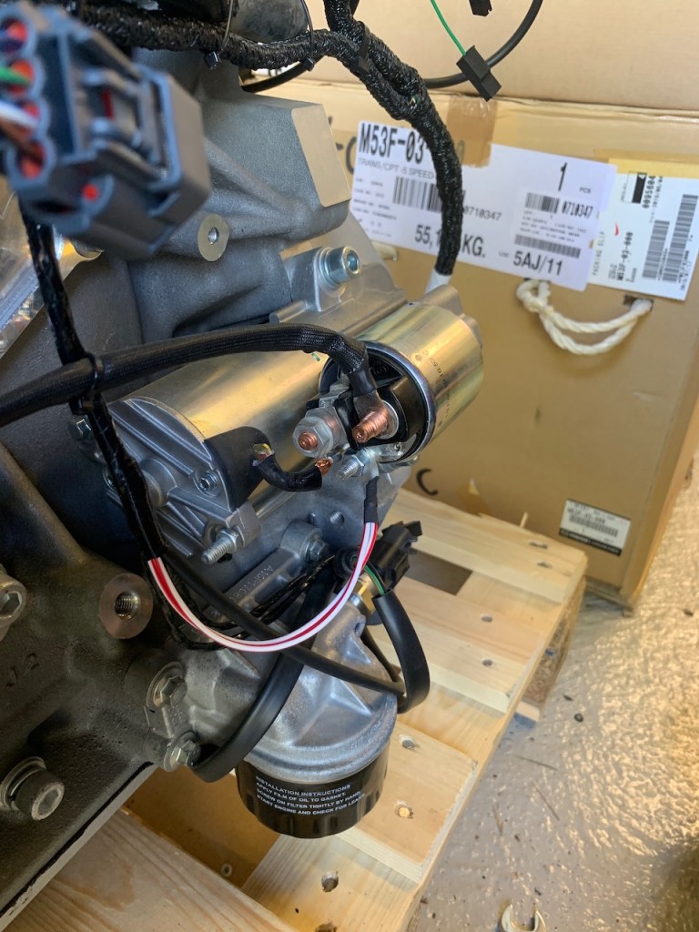
Note the connections 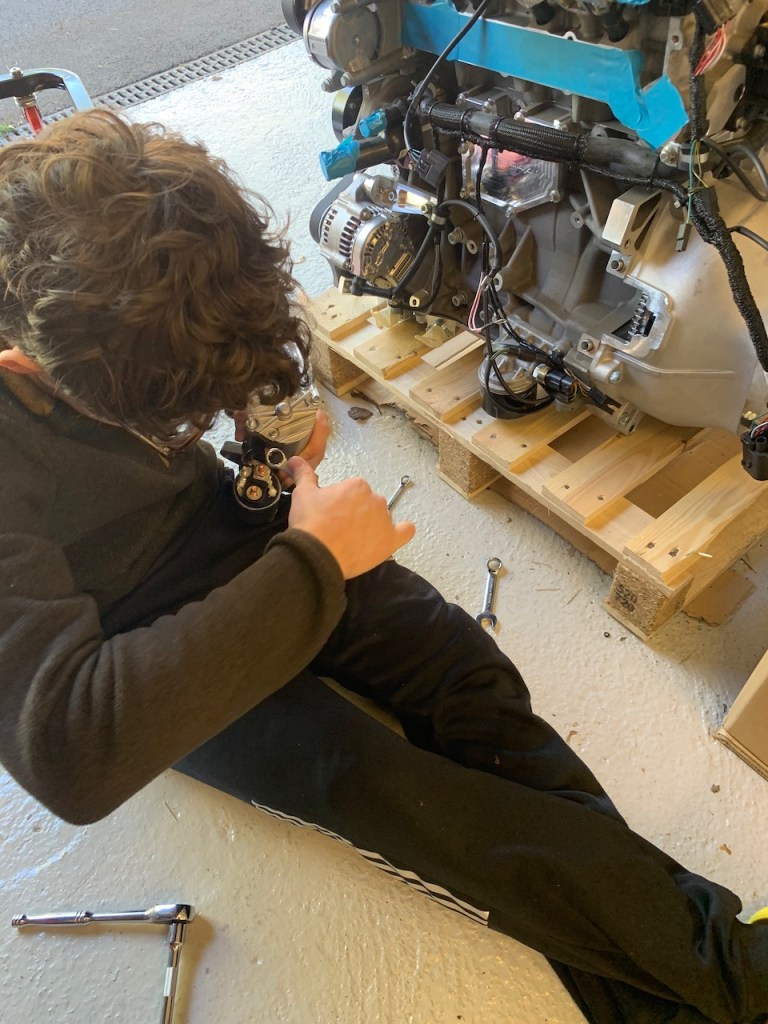
Starter removed
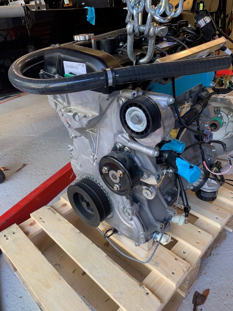
Alternator and Plenum chamber needs to come off too (engine intake and water ports taped over)
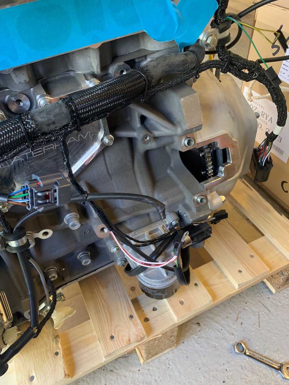
Bellhousing to remove 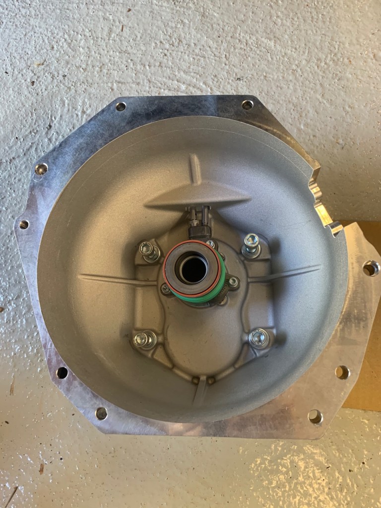
Bellhousing, clutch release bearing/assembly and gearbox bolts 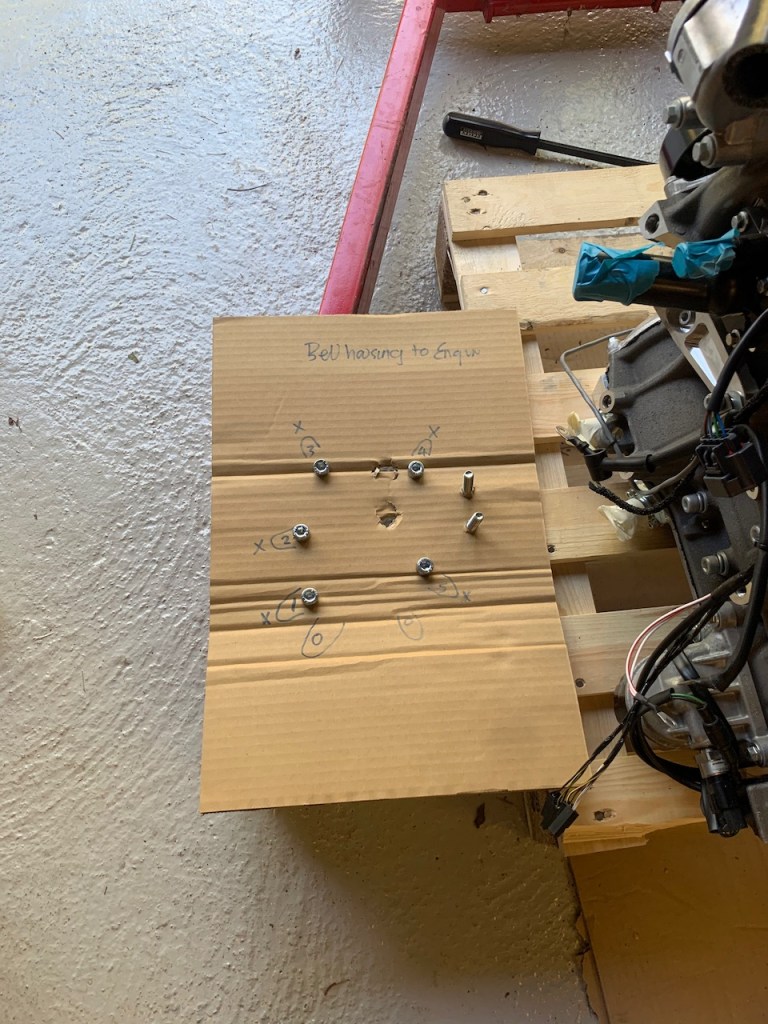
Don’t lose the bolts (these are bell-housing to engine block)
The bellhousing is held on by seven bolts and two dowels. Gentle tapping with a deadblow hammer and even gentler use of a pry-bar was necessary to split the bellhousing from the engine block.
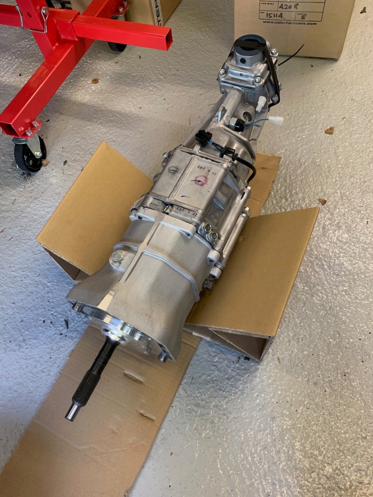
Remove the gearbox from its crate 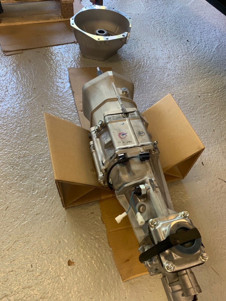
Clear some space to work 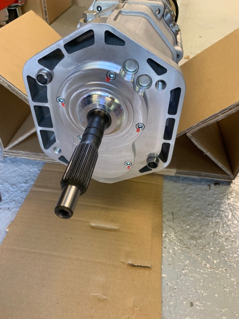
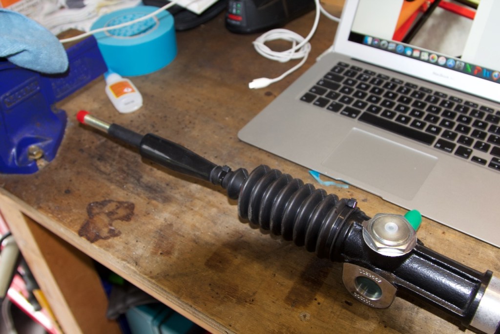
Gearbox input shaft
The four large cap head bolts needed to attach the gearbox to the bell-housing are pre-fitted at the factory. The bolts pass through the bell-housing and into the gearbox and are torqued up to 61Nm.
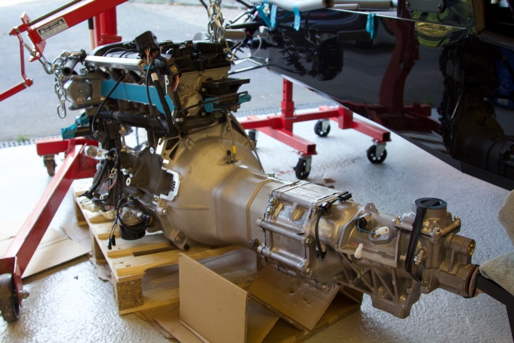
The next part is to mate the gearbox+bell housing to the engine block. This requires some brute force to lift the gearbox+bell-housing, insert the input shaft into the clutch plate and hope that the engine builders have aligned the clutch with the crankshaft pilot bearing (which they had). Once aligned everything slipped into place and the bell-housing was held by the locating dowels.
The seven bolts bell-housing bolts were refitted and and torqued to 47Nm. As the 420R has a dry sump a nylon skid plate also needs to be fitted to the bottom of the engine. The skid plate will be somewhere in the boxes supplied by Caterham and fastens using two cap-head bolts into the face of the bellhousing and two smaller bolts that go up into the dry-sump plate.
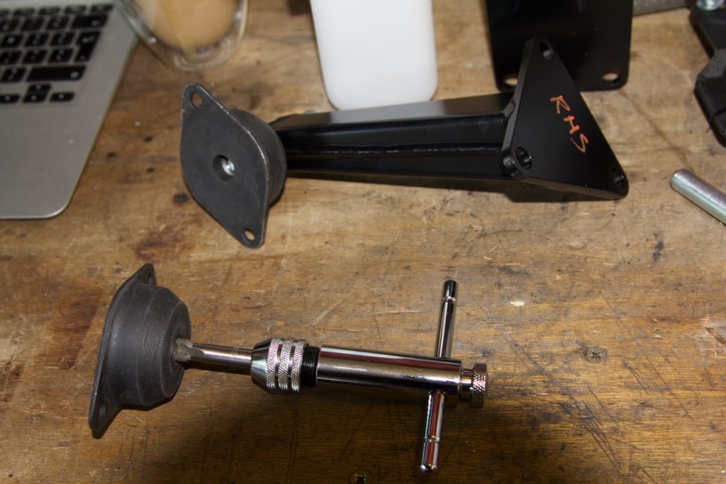
The final job of the day was to clean the threads on the engine mounts. These are rubberised and a fair amount of rubber finds its way into the threads so it is a good idea to run a tap through them at this stage.
Ready for the installation